This article refers to the address: http://
Abstract: A design scheme of 16×16 video switching matrix made with PT2262/PT2272 codec IC is proposed. The specific circuit diagram is given. At the same time, based on the analysis of its principle, it is pointed out that other schemes are derived from this scheme. The basic idea of ​​the specification video switching matrix.Keywords: TV surveillance encoder decoder video switching matrix PT2262 PT2272
With the rapid development of electronic technology, video switchers have been widely used in closed circuit television monitoring systems, television broadcast systems, video conferencing systems, micro-teaching systems, multimedia teaching systems and other fields. The multi-input video switching matrix is ​​an indispensable important device for large-scale CCTV surveillance systems, but the price of such devices is relatively high. Based on the design idea of ​​computer control, this paper chooses cheap remote control decoding integrated circuit (PT2262/PT2262) and multi-channel analog switch chip (CD4067), and adopts a modular structure to design a 16×16 video switching matrix, thus realizing remote control video. The function of switching.
1 Characteristics of PT2262/PT2262
The PT2262 and PT2272 are codec ICs in an 18-pin dual in-line package that are highly resistant to interference. The TP2262 is an encoder that compiles data and addresses into code waveforms. It has a maximum of 12 three-state addresses and a total of 531,441 address codes. It has a maximum of 12 three-state addresses and a total of 531,441 address codes. The PT2272 is a decoder paired with the PT2262. It also has a 12-bit tri-state address with a total of 531,441 address codes. PT2262 and PT2272 are CMOS circuits, so they have low power consumption and wide operating voltage range (3~15V).
1.1 Pin Function of PT2262
The pin functions of the PT2262 are as follows:
A0~A5(1~6): address pins, these pins have three states: "0", "1" and "float";
A6/D0~A11/D5 (7, 8, 10~13): These six pins can be used as both address code pins and data code pins. When used as address code pins, they can be set to " 0", "1" or "float"; when used as a data code pin, it can only be set to "0", "1".
TE (14): Transmit enable, active low. When it is low, the PT2262 outputs an encoded waveform;
DOUT (17): data code output pin;
OSC1, OSC2 (16, 15): oscillator pin;
VSS (18): positive power supply;
VSS (9): Negative power supply.
1.2 PT2272 pin function
The pin functions of the PT2272 are as follows:
A0~A5(1~6), A8/D0~A11~D3(7,8,10~13): These pins have the same function as PT2262;
DIN (14): data input pin;
VT (17): Active transfer pin, active high. When PT2272 receives a valid coded waveform signal, VT becomes high;
OSC1, OSC2 (16, 15): oscillator pin;
VCC (18): positive power supply;
VSS (9): Negative power supply.
Figure 1 16 selected 1 video switching circuit schematic
The data output of PT2272 has two kinds of "temporary storage" and "latch". When the input signal disappears, the data bit output corresponding to PT2272 becomes low level; "latch" is the signal at the input end. When it disappears, the data bit output of PT2272 remains in its original state until it receives a new input with the same address code.
The data output of PT2272 has 4 or 6 bits. It can be distinguished after use: M stands for "temporary memory" and L stands for "latch" (for example, PT2272 L4 indicates that the data bit is output as 4 bits, latch output). When the encoding circuit PT2262 serially transmits the data together with the address code from the 17-pin, it can be transmitted to the 14-pin (data input terminal) of the decoder PT2272 via the double line. At this time, if the address of the decoder is A0-A7 and the encoder The addresses A0 to A7 are the same, and the decoder will receive the transmitted data and display them in parallel at the data output terminals D0 to D3 and latch them, and output a pulse signal at the VT terminal.
2 16 × 16 video switching matrix composition
The 16×16 video switching matrix consists of 16 16-select 1 video switching boards and a motherboard. The 16 video switching boards are plugged into the motherboard through the board sockets. There are 16 video input sockets and a 9-pin socket on the main board. 16 video jacks for 16 channels of video input. The nine-pin socket is used to connect to the 9-bit data cable of the computer print port for encoding on the main board by the encoding circuit composed of PT2262. However, whether it is 16 channels of video, coded signals, DC power and ground, they can provide interfaces to 16 video switching boards through the board socket.
Each video switching circuit board includes a decoding circuit, 16 analog switching circuits, and a video amplifying circuit. There is a video jack output on the back of the board. Figure 1 shows a 16-to-1 video switching circuit diagram. The schematic frame is shown in Figure 2.
In Figure 1, after the coded signal is input from the data input pin (14) of IC1 (PT2272L4), if its address code (preset by the four-bit code switch SW1) is the same as the coded address, the circuit system will output the data from the data pin. (10~13) Output locked data (such as 03H). When the data input port (10~14) of the 16-channel analog switch IC2 (CD4067) receives the 03H data, the analog switch No. 3 is turned on, so that the third video signal input from the seventh pin will be from the I/O. The output of pin 1 of the port is input to the emitter of the common-pole transistor (T1) amplifying circuit via R4 and C1, and finally the amplified video signal is output by the collector. After the video signal is passed through the emitter follower (T2), the 1Vp-p video signal with an output impedance of 75 Ω is output, and the 16-to-1 video switching process is completed. R4 is used to adjust the output amplitude, the resistance is about 1kΩ; C1 is the high frequency compensation capacitor, about 100pF. This circuit is very simple, so the cost of the entire switching matrix is ​​also very low. The addresses of the 16 video switching boards can be set to 0H to FH respectively.
3 coding circuit
Fig. 3 is a schematic diagram of an encoding circuit composed of a PT2262 encoder, by which 9-bit data can be input at a computer print port. The highest bit is the control data, the upper 4 bits of the remaining 8 bits are the address code, and the lower 4 bits are the data code. In general, the upper 4 bits are input to pins 1 to 4 of the encoder IC (PT2262), and the lower 4 bits are input to the data bits 10 to 13. When there is data input, the highest one control data output is high, so that the collector of the inverter T outputs a low level, so that the enable end (14 feet) of the PT2262 is valid, and finally in its coded output. The terminal (17-pin) outputs the serial encoded signal.
4 software programming
4.1 Control interface design
There are two options for the design of the control interface. The first is 16 rows with 16 ammonium bonds per row. The keys in each row are interlocked. The second option is a total of two lines of 16 buttons per line. The first line is the selector button for the switch, the second line is the video output selection button, and the buttons for the two lines are also interlocked.
In the above two schemes, the first scheme can switch images by pressing one button; while the second scheme is to press two buttons, the switcher is selected first, and the image is switched out the second time.
4.2 Data Structure
Using VB or Delphi language to write control software can output 9-bit data in the print port to control the computer to distribute data twice, the first time is the lower 8 bits, the second time is the highest one. Among the lower 8 bits, the upper 4 bits are the address code 0H-FH, which can be used to indicate the address of the 1st to 16th line video switcher, and the lower 4 bits are the data code of 16 selected 1 per line. When the button is pressed on the interface, the data is output when pressed, and the data is reset to zero when released. All data to be latched is implemented by hardware.
In the first scheme, the print port outputs data according to each button; while the second solution only outputs data when the second line is pressed, and the same button has 16 addresses, which depends on the first row of buttons. Which key to set.
5 Conclusion
The video switching matrix is ​​generally used to compare large-scale closed-circuit circuit monitoring systems. The cost of the 16×16 video switching matrix introduced in this paper is very low, and with a slight modification, it can be turned into 16×8, 16×4, 16×2 products. . If it is not required to repeat in several video outputs, it can be easily changed to 256 channels of video input / 16 channels of video output, 128 channels of video input / 8 channels of video output, 64 channels of video input / 4 channels of video output, etc. Specifications of the product.
Since the control computer does not need to process the image, the configuration of the computer is not high, and the computer with 486 or more can be used. If you don't need computer control, you can also change to keyboard control. When realized, two rows of keyboards can be selected, and the structure of each row of 16 buttons can be further reduced. The circuit for controlling the keyboard is also very simple, and will not be described in detail herein.
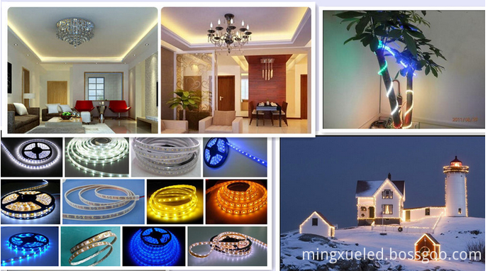
LED5050 strip light of the lamp as a light source is SMD 5050led to FPC board as the carrier circuit in series with the appropriate current limiting resistor design and production of decorative lighting. With high brightness, soft, flexible, you may need to cut to length, etc.
SMD5050 LED Strip Light of the light source LED5050 lamp beads, it means that the length of LED components is 5.0mm, width is 5.0mm, the industry referred to 5050. SMD chip type genus, the carrier is a soft FPC board. That flexible circuit boards, most of the width 10MM, thickness of less than 1MM. Each FPC factory length of 0.5 meters. Can be two or several mutually welded. Produce a good Smd5050 Led Strip Light of the length of the factory 5M roll, anti-static disc and anti-static bag, portable and easy to transport.
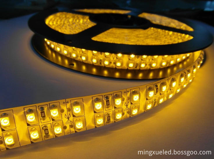
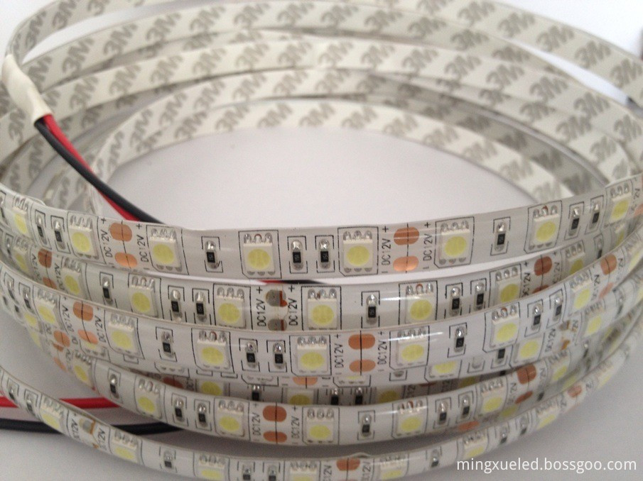
SMD5050 LED Strip Light can be classified from the following aspects:
1. Color: FPC main color yellow board, whiteboard, blackboard, can be customized. SMD5050 Led Strip Light luminous colors: white, warm white, red, yellow, blue, green, purple, colorful, full-color, Symphony.
2. Waterproof: lights due to apply to a different location, water level is divided into not waterproof, Epoxy waterproof, waterproof casing, plastic irrigation water.
3. Lamp beads: on the FPC can be attached to many LED5050 lamp beads, so the per meter FPC, lamp beads per meter 30 lights, 60 lights per meter, 120 lights per meter three general to apply to different brightness requirements The place.
We focus on LED area, is a high-tech lighting enterprise deal in develop, produce and sales.
Owns DIP LED,SMD LED professional production lines and SMD5050 LED Strip Light lines, the produce volume per month for DIP LED,SMD LED is 50 million pieces, for SMD5050 LED Strip Light is 500 thousands meters, for LED flexible strip light for car is about 200 thousands pairs, for LED tube light is 50 thousands pieces, for LED Spotlights are 200 thousands pieces, for LED ceiling light are 50 thousands pieces.
Our R & D team can handle highly customized designs and offer OEM and ODM services.
We hope to set up a long-term partnership with you through our high quality products and our Sincere Service!
Mingxue Optoelectronics Co.,Ltd. has apply the I S O 9 0 0 1: 2 0 0 8 international quality management system certificate, we apply the CE, RoHS and SAA certificate for our led lighting product.
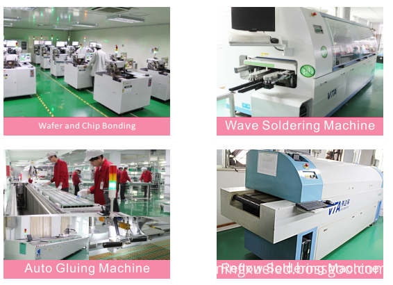

SMD5050 LED Strip Light
Led Strip Behind Tv,Led Office Lighting,Garage Led Strip,Yellow Led Strip
Shenzhen Mingxue Optoelectronics CO.,Ltd , http://www.mingxueled.com