One. Introduction With the widespread use of programmable logic controllers (PLCs) in industrial automation, PLC programming has become an essential skill for electrical engineers. There are numerous PLC brands available on the market, including European, American, Japanese, Korean, and Taiwanese models. While this provides users with a wide range of choices, it also brings some challenges. One common issue is that programming cables for different PLC brands are not interchangeable. Purchasing original cables can be very expensive, often costing thousands of dollars. For users who primarily use PLCs for learning purposes or frequently work with various brands, having a cost-effective DIY programming cable would be highly beneficial.
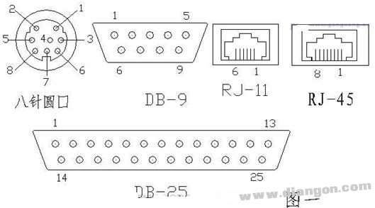
Two. Understanding PLC Programming Interfaces The PLC programming port typically connects to the PC's COM port via a programming cable. On the PC side, this is usually an RS232C interface with a DB-9 connector. On the PLC side, the interface can vary, commonly falling into three main types: RS232, RS485, and RS422. In terms of physical structure, there are five common types: eight-pin round connectors (DIN-8), nine-pin D-shaped ports (DB-9), twenty-five-pin D-shaped ports (DB-25), RJ11 ports, and special interfaces. These are the most common configurations, as shown in Figure 1.
To create a functional programming cable, it’s important to understand the three main serial communication standards: RS-232, RS-422, and RS-485. These standards define the electrical characteristics but not the physical connectors or protocols. Therefore, the same standard can have different physical implementations, such as DB-9 or DB-25. RS-232 is the most widely used in PCs and communications, featuring a 25-pin configuration, though only the main channel (nine pins) is typically used. It supports point-to-point communication but has limited distance and poor noise immunity. RS-485, on the other hand, uses balanced transmission and differential signaling, making it ideal for long-distance communication and industrial environments. It can support up to 32 devices on a single bus and is suitable for half-duplex communication. RS-422 is similar to RS-485 but supports full-duplex communication and is used for longer distances at lower speeds.
Table 1: RS-232 Interface Pin Definitions
| 25-pin | 9-pin | Abbreviation | Description |
|---|---|---|---|
| 2 | 3 | TXD | Transmit Data |
| 3 | 2 | RXD | Receive Data |
| 4 | 7 | RTS | Request to Send |
| 5 | 8 | CTS | Cleared to Send |
| 6 | 6 | DSR | Data Set Ready |
| 7 | 5 | GND | Signal Ground |
| 8 | 1 | CD | CARRIER DETECT |
| 20 | 4 | DTR | Data Terminal Ready |
| 22 | 9 | RI | Ring Indicator |
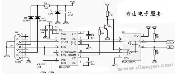
Three. Building a PLC Programming Cable The primary function of a PLC programming cable is to convert the data format from the PLC’s interface (RS485 or RS422) to the PC’s RS232C interface. If the PLC uses an RS232 interface, it can be directly connected. However, for RS485 or RS422, a level conversion circuit or a dedicated interface converter is required. Using a ready-made converter like the SC-485C is a practical solution. This device allows seamless conversion between RS232, RS485, and RS422, and is compact and easy to use. It does not require external power and can be connected directly to the PC’s COM port. The SC-485C is particularly useful when working with different PLC models, as it can adapt to various interface configurations.
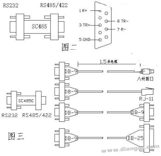
The wiring diagram for connecting the SC-485C to the PLC depends on whether the PLC uses RS485 or RS422. For RS485, pins 3 and 8 are used, while for RS422, pins 3 and 8, along with 1 and 7, are connected. This setup ensures compatibility with multiple PLC models, making it easier to connect and communicate with different systems. The cable is designed to work with both the PC and the PLC, allowing for program uploads, downloads, and real-time monitoring.

Four. Conclusion Using an original PLC programming cable can be costly, but by using an interface converter and custom connectors, you can build a versatile programming cable that works with almost any brand of PLC. These converters are affordable and widely available, making DIY solutions a practical and cost-effective option. A self-made programming cable can perform all necessary functions—such as uploading, downloading, and monitoring programs—without sacrificing reliability or performance. This approach not only saves money but also offers flexibility in handling different PLC models.
Creating a Serial Communication Cable To make a serial communication cable, it’s essential to understand the pin connections based on the interface standard. For example, a 9-pin RS232 cable requires specific cross-wiring between TXD, RXD, RTS, CTS, DTR, and DSR. Here’s a breakdown of the key signals:
- SG: Signal Ground (Common Return)
- TXD: Transmitted Data
- RXD: Received Data
- RTS: Request to Send
- CTS: Clear to Send
- DTR: Data Terminal Ready
- DSR: Data Set Ready
For a 9-pin serial cable, you’ll need two 9-pin plugs and a flat cable with at least seven wires. The pin connections are as follows:
- 9-pin to 9-pin: 2-3, 3-2, 4-6, 5-5, 6-4, 7-8, 8-7
- 9-pin to 25-pin: 2-2, 3-3, 4-6, 5-7, 6-20, 7-5, 8-4
- 25-pin to 25-pin: 2-3, 3-2, 4-5, 5-4, 6-20, 7-7, 20-6
Finally, building a PLC programming cable involves understanding the specific pin layout of each PLC model. Table 2 lists the pin definitions for several popular PLCs, which can help guide your wiring. If a specific model isn’t listed, you can refer to the technical manual or search online for compatible wiring diagrams. By following these guidelines, you can create a reliable and cost-effective programming cable tailored to your needs.
Bare Copper Conductor,Copper Wire,Bare Copper Wire,Copper Conductor
HENAN QIFAN ELECTRIC CO., LTD. , https://www.hnqifancable.com