The car combination switch is a kind of switch commonly used in automobiles (the appearance is shown in Figure 1), with low beam, high beam, small lamp, headlight, overtaking, wiper high speed, low wiper speed, wiper intermittent, washing, left Turn, turn right and other gears. At present, many manufacturers still use the traditional analog test method when testing the combination switch. This method is easy to cause individual gears to miss and misdetect, and the detection efficiency is also low. To this end, the author has made a car combination switch detection device based on AT89S52, which can accurately detect all the gears of the combination switch, and has the function of sound and light alarm, which effectively prevents the wrong detection and individual gears in the simulation test. Missing detection. Here, only the circuit portion of the device is analyzed as follows.
This article refers to the address: http://

Figure 1 common switch
First, the overall program design
Combination switch detection is a very important part of production. Generally, the analog detection method is adopted. All the peripheral circuits of the combination switch are installed on the test bench, and the indicator lights are used to simulate the working condition of each gear. For example, the combination switch is pulled to the intermittent gear. Bit, the indicator should flash intermittently. This type of inspection is highly demanding for workers and is very likely to cause false and missed inspections. The combination switch detection device designed and manufactured by the author adopts the detection scheme of single-chip scanning, adds sound and light alarm, reduces the labor intensity of workers, effectively prevents false detection and missed inspection, and is especially suitable for production site use. The circuit is shown in Figure 2.

Figure 2 circuit physical
Second, the circuit design principle
The detection device adopts the AT89S52 which is common in the market as the MCU. The chip is simple to program, convenient to download, and cost-effective, and is widely used in the industrial control field. The detection device is provided with a ten-level qualified indicator light and an overall qualified indicator for a certain type of combination switch, and the overall qualified indicator light is illuminated when all ten gears are tested. In addition, in order to concentrate the attention of workers to prevent misjudgment, an overall qualified audible alarm is also set, and the alarm is issued by voice while the overall qualified indicator is lit.
1. Hardware design
The hardware circuit of the detection device is shown in Figure 3.

Figure 3 detection device hardware circuit
The PO and P1 ports are used as external switches for the combination switch, and the external leads of the combination switch are the external lead wires of the respective gear switches. When the combination switch is dialed to a different gear, each lead is turned on or off as required.
P2 port and P3.0, P3.1, P3.6 are used as qualified alarm indications. This is just a simple LED indicating circuit. If the indication is more obvious, the power driving display circuit can be enlarged by the high-power indicator expansion port.
The P3.2 port is connected to the probe switch. When the combination switch is pressed on the test tool, the probe switch will be closed at the same time, and the detection device will start detecting.
P3.7 external recording and playback module, there are many such modules on the market for selection. This article selects the recording and playback module with ISD4004-08 as the core (Figure 4). The module comes with a power amplifier circuit composed of LM386, which can record 16 segments and 480s of recordings. It only needs to add 15ms~30ms negative pulse signal to the corresponding port to play the recording. The operation is very convenient.

Figure 4
2. Software design
The system uses the method of point-to-point scanning of each gear of the combination switch to judge whether the switch is good or bad, and also detects whether the internal wiring of the combination switch is correct and whether there is a short circuit between the leads. At the same time, in order to improve the test efficiency, the automatic test function is also added. When the combination switch is taken, the system automatically resets. After the next combination switch to be tested is placed, the system automatically starts detection. The program flow chart is shown in Fig. 5.

Figure 5 program flow chart
Third, installation and use
After the circuit board shown in Figure 2 is connected to the peripheral leads, the combination switch presses the probe switch, and the system automatically starts the test. In this case, the combination switch is sequentially turned to each gear. When the gear is normal, the corresponding indicator lights up. When all the gears are qualified, the total qualified indicator lights up and the voice alarms. The detection device has been applied to the production site and the detection effect is very good.
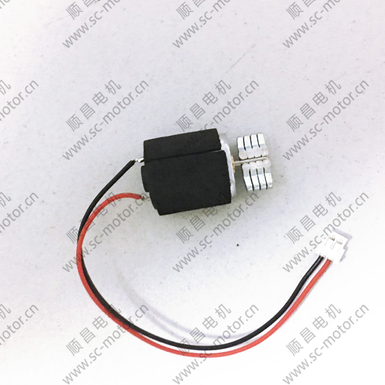
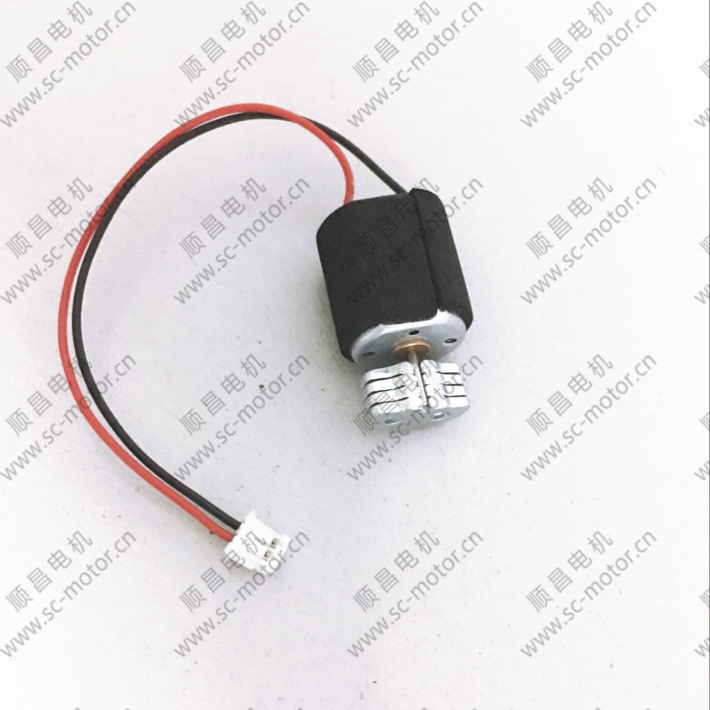
Cosmetic Instrument Vibration Motor Mainly used in cosmetic instrument, such as instrument, cleansing essence introducing vibration meter, wash a face, facial massage, hairdressing instrument, etc.


Operating temperature range:
Cosmetic Instrument Vibration Motor should be used at a temperature of -10~60℃.
The figures stated in the catalog specifications are based on use at ordinary room temperature catalog specifications re based on use at ordinary room temperature (approximately20~25℃.
If a Cosmetic Instrument Vibration Motoris used outside the prescribed temperature range,the grease on the gearhead area will become unable to function normally and the motor will become unable to start.Depending on the temperature conditions ,it may be possible to deal with them by changing the grease of the motor's parts.Please feel free to consult with us about this.
Storage temperature range:
Cosmetic Instrument Vibration Motor should be stored ta a temperature of -15~65℃.
In case of storage outside this range,the grease on the gearhead area will become unable to function normally and the motor will become unable to start.
Service life:
â—Use with a load that exceeds the rated torque
â—Frequent starting
â—Momentary reversals of turning direction
â—Impact loads
â—Long-term continuous operation
â—Forced turning using the output shaft
â—Use in which the permitted overhang load or the permitted thrust load is exceeded
â—A pulse drive ,e.g.,a short break,counter electromotive force,PWM control
â—Use of a voltage that is nonstandard as regards the rated voltage
â—Use outside the prescribed temperature or relative-humidity range,or in a special environment.
â—Please consult with us about these or any other conditions of use that may apply,so that we can be sure that you select the most appropriate model.
when it come to volume production,we're a major player as well .each month,we rurn out 600000 units,all of which are compliant with the rohs directive.Have any questions or special needed, please contact us, we have the engineer group and best sales department to service to you Looking forward to your inquiry. Welcome to our factory.

Cosmetic Instrument Vibration Motor
Cosmetic Instrument Vibration Motor,Face Brush Vibration Motor,Electric Cosmetic Instrument Vibration Motor,Cosmetic Instrument Mini Vibration Motor
Shenzhen Shunchang Motor Co., LTD. , https://www.scgearmotor.com