introduction
The PCI bus is widely used in computers because of the large data throughput of the bus and because the bus is independent of the specific processor. The allocation of PCI hardware device resources is not determined by the hardware design, but is allocated by the Windows operating system according to the possession of resources by all hardware devices in the PC. This requires designing device drivers to operate on physical hardware across the boundaries of the operating system.
1 PCI interface features integrated in the DSP chip
1.1 Internal structure of the PCI interface
The DM642 integrates a PCI interface in master/slave mode, which is equivalent to a dedicated PCI interface chip. This eliminates the need to delve into the PCI bus specification and focuses on the implementation of system functions. The DSP can interconnect with the PCI host through this interface.
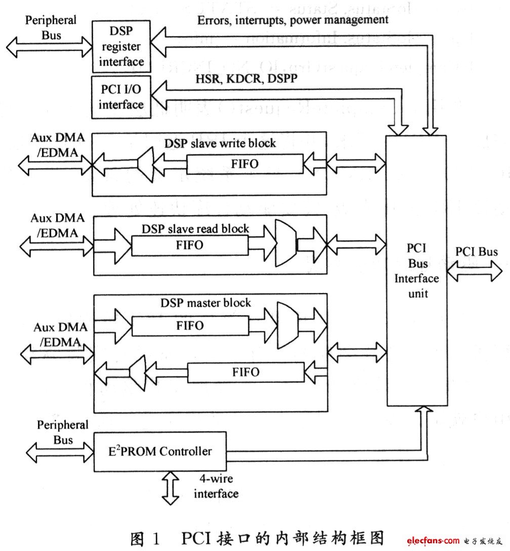
As can be seen from Figure 1, the internal structure of the PCI interface consists of seven parts:
(1) PCI Bus Interface Unit (PBIN): This module does not insert a waiting period for bus transactions in master/slave mode, which can achieve the maximum bus transmission bandwidth.
(2) E2PROM controller module: The controller is connected to an external 4-wire serial E2PROM. When the PCI interface is reset, the controller reads the data in the E2PROM and configures the PCI interface. The DSP can access the E2PROM through the map registers.
(3) DSP slave mode write module: including a multiplexer and a PBIN to DSP FIFO. Its completed function is: the external PCI device writes data to the DSP slave device through the PCI interface. When the external master performs a write operation to the Base0 space of the DSP, the PCI address is combined with the fixed offset value in the DSPP register to form the DSP destination address, and the destination address is automatically incremented during the transmission.
(4) DSP slave mode read module: including a multiplexer and a DSP to PBIN FIFO. Its function is: the external PCI device can read data from the DSP slave device through the PCI interface. When the external master performs a read operation from the Base0 space of the DSP, the PCI address is combined with a fixed offset value in the DSPP register to form the DSP source address, which is automatically incremented during the transfer.
(5) DSP main mode module: including reading/writing two sub-modules, DSP is the main controller of the module. The DSP master mode reads this sub-module, and the DSP master device reads data from the external PCI slave device through the PCI interface. The DSP master mode writes this sub-module to complete the DSP master device writing data to the external PCI slave device through the PCI interface.
(6) PCI I/O interface module: It includes PCI I/O registers, HSR, HDCR, DSPP. It can only be accessed by the PCI host through the spatial mapping of the base 1 register or the base 2 register.
(7) DSP register interface module: contains the mapping register of DSP, which is used to control the main mode interface, generate PCI interrupt and power management.
Several other modules are connected to the PCI bus interface module, and the PCI bus interface module is externally connected to the external device through the PCI bus. The DSP can perform data transfer with the external device by reading or writing in the master/slave mode.
1.2 Registers in the PCI interface
The PCI interface includes three types of registers:
(1) PCI configuration register: can only be accessed by an external PCI host (Host).
These registers provide configuration information for the PCI interface and can only be accessed by external hosts, can be loaded automatically from an external E2PROM, or set directly to default values.
(2) PCI I/O registers: can only be accessed by an external PCI host (Host).
The PCI I/O registers can only be accessed by the PCI host through a spatial mapping of the Basel Address Register or the Base2 Address Register.
(3) The PCI register mapped in the DSP peripheral space is used for DSP control. The PCI interface can be accessed by an external PCI host or by a DSP.
2 driver design
The device driver provides a software interface to the computer hardware. It is the trusted part of the operating system and is managed and mobilized by the I/O Manager (I/O Manag-er).
User applications access the hardware in a standardized way, regardless of how the hardware is controlled. The driver always makes the device look like a file, can open a handle to the device, and the application can issue read and write requests to the driver before the device handle is finally closed.
Each time the I/O Manager receives a request from a user application, it creates an I/O Request Packet (IRP) data structure and passes it as a parameter to the driver.
2.1 Components of the device driver
Think of a complete driver as a container that contains many routines. When the operating system encounters an I/O Request Packet (IRP), it calls the routines in this container to perform various operations on the IRP. The driver contains the following basic routines:
(1) DriverEntry routine: It is the initialization entry point of the driver and must be called DriverEntry. It is responsible for the initialization of the driver and is used to initialize the data structures and resources within the scope of the driver. It mainly has the following three functions: setting the entry pointer of Adddevice, Unload and other routines; you can get some required information from the registry to initialize the driver; initialize other data structures and resources within the scope of the driver. All drivers must include it. When the driver is loaded, the PnP Manager calls the DriverEntry routine once for each driver.
(2) AddDevice routine: After the driver is initialized, the PnP manager calls the driver's Add Device routine to initialize the device controlled by the driver. In the Add Device routine, the driver creates a device object as the target device and attaches the device object to the device stack.
(3) PnP routines: PCI devices are plug-and-play devices, and drivers for PCI devices must have PnP routines. The PnP Manager uses PnP routines to manage driver startup, stop, and delete devices.
(4) Dispatch: It is used to manage the communication between the driver and the application, thereby realizing the purpose of the application controlling the PCI device.
Strictly speaking, only the "initialization" module Drivet-Entry routine in the driver must be indispensable. In practice, all drivers have a distribution routine that handles user I/O requests.
Crawler tractors are versatile,domestic initiative and technology leading. Hydraulic controlled differential - brake turn to technology , 360 degree steering wheel control and spin turn are our company`s unique advantages. In addition, our products also have the superiorities of triangular track drive, low grounding pressure and better Paddy field performance. Our company has iron crawler tractor and Rubber Crawler Tractor, which two main products. Every products have different types. These products are of high efficiency, long operating life. and low fuel consumption. Our crawler tractors are easy switching between hydraulic infinitely variable speed and mechanical transmission.
If you have any questions, please contact with us directly. Crawler tractors are produced by our company with high quality and good appearance. Welcome you can visit our factory.for inqury, Please send mail directly to us!
Rubber Crawler Tractor
Small Crawler Tractor,Rubber Crawler Tractor,Triangular Crawler Structure,Convenient Control Crawler Tractor
Hunan NongFu Machinery&Electronic.Co., Ltd. , https://www.nfagmachine.com