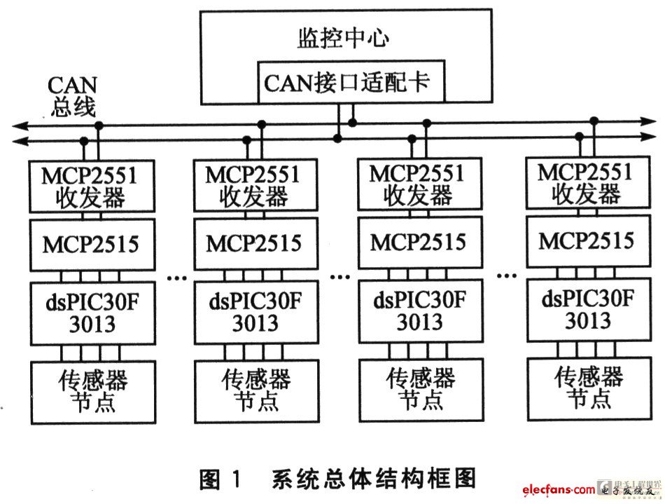
In industrial control, in order to ensure the reliable operation of the system, it is necessary to detect surrounding environmental variables (such as temperature, air pressure, humidity, etc.). The usual practice is to connect the signals collected by the sensors distributed everywhere to the monitoring center through their respective lines. This way, the task of effectively completing the detection task also causes a great waste of line resources. Therefore, a requirement for simplifying the layout of the line has been proposed. CAN (Controller Area Network) is a serial communication protocol that can effectively support distributed real-time control of high security levels. At the same time, in theory, there are almost no restrictions on nodes in the CAN bus network. Based on this, the CAN bus data acquisition system based on digital signal controller is used as a CAN node. Each CAN area is placed in a monitoring area, and each node communicates with the monitoring center through the CAN bus. The overall block diagram of the system is shown in Figure 1.

1 hardware composition
The data acquisition system consists of two parts: the control part, including the anti-aliasing filter of the front-end signal and the 12-bit analog-to-digital converter for signal acquisition; the CAN bus interface circuit part, by the MCP2515 CAN protocol controller and the MCP2551 high-speed CAN The transceiver is constructed. The system is connected to 3 signals, and the TEM, PRE, and RH are temperature, air pressure, and relative humidity, respectively.
1.1 Control section
The dsPIC30F3013 is a family of sensor digital signal controllers from Microchip. The controller features a 16-bit (data) modified Harvard architecture with an enhanced instruction set that includes powerful support for the DSP. It operates at speeds up to 30 MIPS and integrates a 10-channel 12-bit analog-to-digital converter with a maximum conversion speed of 200 ksps.
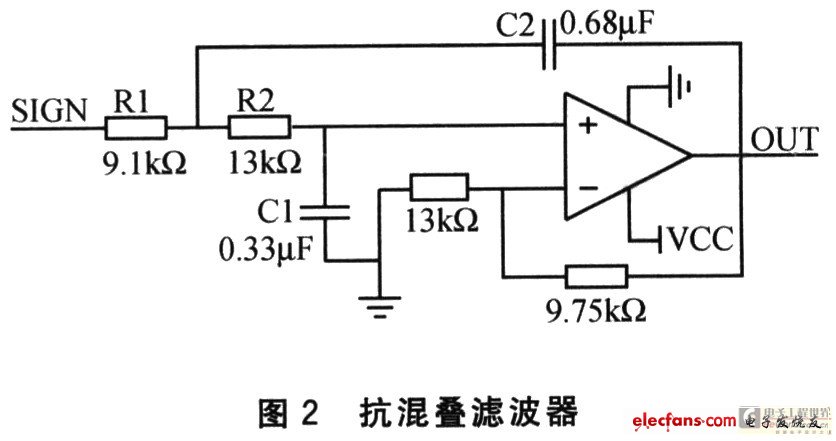
In the industrial control system, due to the existence of various types of noise, an anti-aliasing filter circuit needs to be added to the signal acquisition end, as shown in Figure 2.

Anti-aliasing uses a Sallen Key second-order low-pass filter. Since the environmental variables are all slow variables, the filter bandwidth is set to 30 Hz. The values ​​of R1, R2, C1, and C2 in the circuit determine the characteristic frequency f0 of the anti-aliasing filter, while also ensuring a resolution of 12 bits at a 10 ksps analog-to-digital conversion rate. In order to pass the signal well throughout the passband, the quality factor Q of the Sallen Key filter needs to be adjusted. The Q value is determined by equation (1):
The amplitude-frequency characteristics of the Sallen Key filter show that the frequency characteristics are optimal when the quality factor is between 0.7 and 0.9. This Q value is selected to be 0.8.
Data acquisition was performed using the 12-bit ADC module of the dsPIC30F3013. Cyclic scanning of three environmental signals produces an interrupt every 12 samples/conversions. During the interruption process, the average value digital filtering and the format adjustment of the corresponding parameters are completed, and then transmitted to the CAN protocol controller through the SPI interface.
Zysen offer 4-Way Power Divider(Combiner, power splliter) from 500MHz-40GHz, Conntector SMA,N,2 92mm are available, frequency band can be customized, contact us with your requirement:sales@zysentech.com.
4 Way Divider,Rf Splitter Combiner,4 Way Power Divider,Power Divider Combiner
Chengdu Zysen Technology Co., Ltd. , https://www.zysenmw.com