1. Check the quality of the serial cable
1) Plug the serial cable into the computer, and short-circuit the pins 2 and 3 of the serial port with a short circuit
2) Open the serial debugging assistant
3) Click Auto Send, and send a random data in the window of automatic sending to see if you can receive the data sent by yourself, indicating that the serial port line is normal, otherwise it is bad.
2. After downloading the microcontroller program, see if there is data sent out from the serial port to detect
3. The meaning of the 4 lights communicated with the module on the single chip microcomputer
1) DO lamp
Flashing all the time means that the serial communication between the serial port of the microcontroller and the GSM module is abnormal, otherwise the serial communication is normal
2) D1 light
When the light is on, it means that the module is registered on the network, otherwise it is not registered on the network
3) D2 light
Light on means to start texting
4) D3 light
Light on means texting is over
4. The connection between the single-chip board and the GSM module
SCM --------- GSM module
VCC -------- vcc (P3 pin 3)
GND -------- GND (P4 pin 4)
RX_232 (indicating the sending of the single-chip microcomputer) ---------- RXDPC_232 (the receiving of the module (P5 pin 5))
TX_232 (indicating the reception of the single chip microcomputer) ---------- TXD_PC232 (transmission of the module (P6 pin 6))
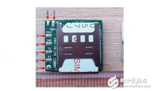
gsm module and single chip microcomputer connection
The single-chip computer is connected to the GSM module directly by connecting the TX and RX of the asynchronous serial communication port. Don't forget the ground wire.
Precautions:1. Different MCUs have different voltages. The input and output level of the GSM module is 2.85V, and the level of the 51 series is 5V. Generally, a 2K resistor is connected in series on the TX line of 51 output. If it is a 3.3V MCU, this resistance can be very small, a few hundred ohms.
2. The power supply of the GSM module itself and the SIM card circuit are very troublesome. First of all, most GSM modules use the FPC40 interface. The spacing of the cable is only 0.5 mm, and it is a plastic shell, which is not easy to weld. If the welding is not good, the work is unstable. Secondly, the power supply part is more troublesome, the GSM module has a larger emission current, and the maximum instantaneous current is 2A! Therefore, the power supply part generally needs to use a large current DC-DC converter such as LM2576 to provide a voltage of 4V. The design of the DCDC circuit itself is not easy, and the personal application is relatively difficult, and a circuit board is required. Unstable lap. There is also the SIM card part. The communication between the SIM card and the GSM module itself is a complex high-frequency process, and the circuit has strong anti-interference ability. I once tried to connect them with wires, and it fell off within ten minutes. Therefore, the SIM card part also needs to be carefully designed, not to mention that there are only five data lines.
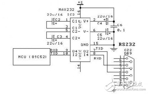
Method of single-chip computer controlling TC35GSM module
1. Hardware connection
For the circuit see the figure below, only need to design a TTL to RS232 level circuit, connected to the UART port of the MCU, and the other end is directly connected to the TC35.
Aluminum Zinc Alloy Die Casting Blank
Aluminum Zinc Alloy Die Casting Blank,Metal Structure Zinc Casting,Custom Made Precision Die,Zinc Aluminum Alloy Casting
Dongguan Metalwork Technology Co., LTD. , https://www.dgdiecastpro.com