|
| Frequency-stabilized frequency modulation signal transmission circuit | | | | The circuit shown in Figure 1 can transmit audio signals to remote locations in a frequency-modulated (FM) manner. 
In the figure, VT1, R2, R3, C2, C3, L1, and Cx form a capacitive three-point frequency modulation oscillation circuit with a resonance frequency between 88MHz and 110MHz. The microphone B converts the sound signal into an electrical signal and sends it to the base of the triode VT1 through the coupling capacitor C1. At this time, the base voltage of VT1 will change with the change of the audio signal, so the collector capacitance of VT1 also changes accordingly, causing the oscillation frequency of the oscillator to change accordingly, to achieve the purpose of frequency modulation. The VT1 collector load L1, Cx, C3 and other tuning loops determine the oscillation frequency (ie, transmission frequency) of the high-frequency oscillator. Since the parameters of C3 and L1 are fixed values, the capacitor Cx is the oscillation frequency adjustment capacitor. Adjusting the capacitor Cx can Change the transmitting frequency of the transmitter, when the capacitance of Cx is 12.5pF, the transmitting frequency is about 108MHz.
The frequency-modulated signal containing the sound signal is output from the collector of VT1 and is transmitted into the air by the transmitting antenna. The antenna is connected to the collector of VT1, and the transmission effect is best when the length is about 690mm. 
The inductance of L1 is 0.17μH, if you can't buy the finished inductor, you can also wind it yourself. The inductance of the winding inductor is related to the diameter, length and number of turns of the coil bobbin, as shown in Figure 2. In the figure, r represents the radius of the skeleton (in mm), x represents the length of the coil after molding (in mm), n represents the number of turns of the coil, and the inductance is n2 × r2 / (228.6r + 254x) (μH) . According to the above method, the inductance L1 is wrapped with a φ0.1mm enameled wire on a round wooden rod with a diameter of 6.7mm for 5 to 6 turns, and then the tire is removed and the coil length is pulled to 6.4mm. |
|
In-depth analysis of the first-level cache and second-level cache of the technical zone CPU eMMC mass burning dilemma, do you really know? Isolation flyback and non-isolated BUCK application design plan Schottky barrier diode selection and application guide How to use Altium in program design Designer puzzle?

Follow WeChat
Interesting and informative information and technical dry goods

Download Audiophile APP
Create your own personal electronic circle

Follow the audiophile class
Lock the latest course activities and technical live broadcast
related suggestion
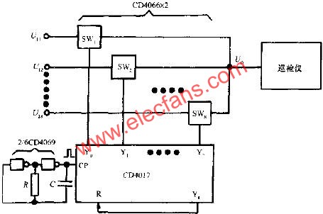
Multi-signal patrol detection transmission circuit
The circuit is shown in the figure. Set the input signal to be divided into 8 channels: U11 ~ U18, two CD4066 are needed. The control signal is sent by CD4017 ...
Posted at 2010-12-06 13:29 • 312 times read
Resistance monitoring of transmission circuit through isolation layer
Abstract: This circuit monitors noisy resistance values ​​or other harsh environments. In the connection of the secondary winding of the entire isolation transformer, the unknown resistance is reflected to the main ...
Posted at 2010-11-19 10:01 • 244 times read
Design of transmission circuit in remote ground sensor system
Design of the transmission circuit in the remote ground sensor system 0 Introduction The wireless sensor network is a kind of RGS system (remote ground transmission ...
Published on 2010-01-12 10:53 • 245 times read
Electromagnetic fully isolated DC power transmission circuit based on capacitance
Capacitor-based electromagnetic fully isolated DC power transmission circuit Keywords: Electromagnetic interference switching power supply Abstract: This paper proposes ...
Published on 2009-11-13 19:00 • 330 views
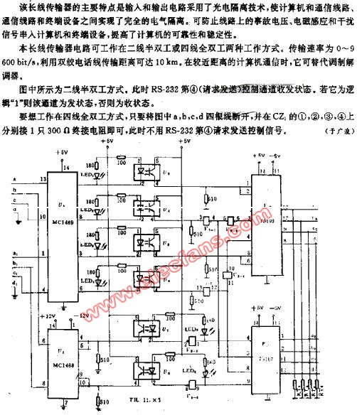
Double-channel long-line transmission circuit
Double-channel long-line transmission circuit
Posted on 2008-12-22 02:30 • 221 times read
[Photo] High-fidelity FM audio signal transmission circuit
Posted at 2006-04-15 20:58 • 447 times read
![[Photo] High-fidelity FM audio signal transmission circuit](http://i.bosscdn.com/blog/20/06/41/5205835846.gif)