NE605 is a high-performance FM receiver chip produced by Philips. It mixes the FM radio frequency signal, amplifies, limits and discriminates the IF radio frequency signal, thereby obtaining the audio output and indicating the strength of the received signal. Based on the introduction of the characteristics, functions and structure of NE605, the paper mainly introduces the actual circuit of the TV field strength meter composed of NE605.
Keywords: RF reception, audio output, IF amplification, NE605
NE605 is a high-performance FM receiver chip launched by Philips in the Netherlands. The chip mixes the received FM radio frequency signal, amplifies the intermediate frequency, limits and discriminates the frequency, thereby obtaining the audio output and the output of the received signal strength indication. The FM receiver composed of NE605 has the advantages of simple circuit, convenient debugging, stable performance and low price, so it can be widely used in mobile communication receivers and radio frequency meters.
1 Features
The characteristics of NE605 are as follows: 
â— Low power consumption, the typical working power supply is 5.7mA when the power supply is 6V;
â— The mixer input frequency is greater than 500MHz;
â— At 45MHz, the frequency conversion power gain of the mixer is 13dB, and the noise figure is 4.6dB;
â— XTAL oscillator frequency can reach 150MHz, LC oscillator frequency can reach 1GHz;
â— Intermediate frequency amplifier / limiter gain is 102dB;
â— The small signal bandwidth of the limiter is 25Mz;
â— RSSI circuit is a logarithmic voltage amplifier with temperature compensation, and the dynamic range exceeds 90dB;
â— There are two kinds of audio output: static noise frequency output and non-quiet noise frequency output;
◠High sensitivity: In the case of 1kHz audio signal (radio frequency is 45MHz and intermediate frequency is 455kHz), the signal-to-noise zero loss ratio (SINAD) is 12dB. For a 50Ω matching network, the sensitivity is 0.22μV.
â— The main performance of 2NE605
â— 2.1NE605 pin function
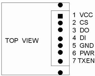
â— NE605 has three package types: DIP-20, SOL-20 and SSOP-20. The pin arrangement is shown in Figure 1. The pin functions are as follows:
1 pin (RF IN): RF input terminal, the typical frequency of the input RF signal is 500MHz;
2 feet (RF BYPASS): RF bypass end;
3 feet (XTAL OSC1): oscillator output;
4 feet (XTAL OSC2): oscillator input;
5 feet (MUTE IN): squelch input terminal; 
7 feet (RSSI OUT): the output end of the received signal strength indicator;
8 feet (MUTED AUDIO OUT): static noise frequency output terminal;
9 feet (UNMUTED AUDIO OUT): non-quiet noise frequency output terminal;
10 feet (QUADRATURE IN): quadrature discriminator input;
11 feet (LIMITER OUT): limiter output;
12, 13 feet (LIMITER DECOUPLING): limiter decoupling end;
14 feet (LIMITER IN): limiter input;
16 feet (IF AMP OUT): intermediate frequency amplifier output;
17, 19 feet (IF AMP DECOUPLING): intermediate frequency amplifier decoupling terminal;
18 feet (IF AMP IN): IF amplifier input terminal;
20 feet (MIXER OUT): mixer output;
6 feet (VCC): positive power supply terminal. The power supply voltage is 4.5 ~ 8.0V;
15 feet (GND): ground.
2.2 NE605 internal structure
The internal functional block diagram of NE605 is shown in Figure 2. It is mainly composed of mixer, oscillator, intermediate frequency amplifier, limiter, RSSI circuit, frequency discrimination and squelch switch. Among them, the mixer is used to input RF The signal is internally mixed with the internal LO signal to obtain a 455kHz intermediate frequency signal. The role of the oscillator is to generate a local oscillator signal through an external crystal or LC phase shift network. The intermediate frequency amplifier is used to amplify the intermediate frequency signal output by the mixer. The limiter is used to limit the signal output by the intermediate frequency amplifier. One channel of the output is connected to the internal frequency discriminator, and the other channel sends the limiter to the RSSI circuit. The RSSI circuit can log-amplify the limiting amount of the limiter to obtain a voltage signal proportional to the input RF level. The frequency discriminator circuit detects the frequency-modulated intermediate frequency signal with a quadrature detector to obtain an audio output signal.
2.3 Main parameters of NE605
The main parameters of NE605 are shown in Table 1.
Table 1 Main parameters of NE605
| Mixer / oscillator section | ||||||
| parameter name | symbol | unit | Test Conditions | Minimum value | Typical value | Maximum |
| Input signal frequency | fIN | MHz | 500 | |||
| Crystal oscillator frequency | fOSC | MHz | 150 | |||
| Noise Figure | dB | Fin = 45MHz | 5.0 | |||
| Third-order input blocking point | dBm | f1 = 45.0MHz, f2 = 45.06MHz | -10 | |||
| Frequency conversion power gain | dB | Match 14.5dBμ boost | 10.5 | 13 | 14.5 | |
| RF input resistance | kΩ | Single-ended input | 3.5 | 4.7 | ||
| RF input capacitance | pF | 3.5 | 4.0 | |||
| Mixing output resistance | kΩ | 20 feet | 1.3 | 1.5 | ||
| IF section | ||||||
| parameter name | symbol | unit | Test Conditions | Minimum value | Typical value | Maximum |
| IF amplifier gain | dB | 50Ω signal source | 39.7 | |||
| Limiter gain | dB | 50Ω signal source | 62.5 | |||
| Input limit (-3dB) | dBm | -113 | ||||
| AM suppression | dB | 80% AM 1kHz | 30 | 34 | 42 | |
| Audio level | mV | 110 | 150 | 250 | ||
| Non-quiet frequency level | mV | 480 | ||||
| SINAD sensitivity | dB | RF level is equal to -118dBm | 16 | |||
| Total harmonic distortion | dB | -35 | -42 | |||
| Signal to noise ratio | dB | No modulation of noise | 73 | |||
| IF RSSI output | mV | IF level is -118dBm | 0 | 160 | 550 | |
| V | IF level is -68dBm | 2.0 | 2.5 | 3.0 | ||
| V | IF level is -18dBm | 4.1 | 4.8 | 5.5 | ||
| Scope of RSSI | dB | 90 | ||||
| RSSI accuracy | dB | ± 1.5 | ||||
| IF input impedance | kΩ | 1.4 | 1.6 | |||
| IF output impedance | kΩ | 0.85 | 1.0 | |||
| Limiter input impedance | kΩ | 1.4 | 1.6 | |||
| Audio output impedance | kΩ | 58 | ||||
| RF / Audio section | ||||||
| parameter name | symbol | unit | Test Conditions | Minimum value | Typical value | Maximum |
| Non-quiet frequency level | mV | Valid value when Vcc = 4.5V, RF level = -27dBm | 450 | |||
| System RSSI output | V | Vcc = 4.5V, RF level = -27dBm | 4.3 | |||
3 Typical application of NE605
3.1 Circuit composition
Figure 3 shows the circuit of the TV field strength meter formed by NE605. The entire circuit mainly includes the following parts;
a. RF signal processing circuit
The TV radio frequency signal is sent to the radio frequency input end of the high-frequency head through the antenna or the coaxial line, and after the first frequency conversion is completed by the high-frequency head TDQ-3, the first intermediate frequency signal 36.455MHz is output. K1 is the band selection switch, W1 is the AGC potentiometer, and W2 is the tuning potentiometer.
b. IF signal processing circuit
The first intermediate frequency signal is added to the input of NE605 through the resonant network composed of C3, C $ and LC2, and NE605 performs the second frequency conversion, amplification, limiting and frequency discrimination. L4 is the frequency discrimination coil. FLT1, FLT2 and 455kHz three-terminal filter, composed of C6 ~ C8, L3 and X1 constitute the local oscillator phase shift feedback network, K3 is a noise suppression switch.
c. RSSI output circuit 
The RSSI voltage signal output by NE605 is filtered by C26 and divided by W3 and then added to DPM for display.
d. Audio amplifier circuit
The audio signal output by EN605 is amplified by LM386 and drives the speaker SP. K4 is the squelch / non-squelch sound selection switch, W4 is the volume potentiometer, and R5 and C19 form a de-emphasis circuit.
e. Power supply circuit
For the convenience of field use, the instrument can be powered by a 12V storage battery or a rechargeable battery pack. A DC-DC generates a tuning voltage of 32V, and a three-terminal regulator outputs 9V and 6V.
3.2 Commissioning instructions
The circuit is simple to assemble, as long as the connection is correct, it can work when powered on. When debugging the circuit, first adjust L4 until the sound quality of the received TV sound is the best; then adjust W1 and W3 so that the DPW indication matches the level of the input RF signal.

Follow WeChat

Download Audiophile APP

Follow the audiophile class
related suggestion
Abstract: ADV7183 is an enhanced video decoder with 10-bit ADC integrated by American Analog Devices (ADI). Inside it ...
Abstract: IME6400 is an integrated circuit developed by South Korean INTiME that can support MPEG4 high-resolution real-time video encoding ...
Three-terminal ...
![[Photo] Three-terminal voltage regulator XWY2005 and its application](http://i.bosscdn.com/blog/20/06/41/7212011242.jpg)
...
High Accuracy CMOS Operational A ...
![[Photo] High-precision CMOS operational amplifier LMC6062 / ...](http://i.bosscdn.com/blog/20/06/41/6175842568.gif)
Abstract: NCP1
![[Photo] Single-ended PWM controller NCP1205 and its application](http://i.bosscdn.com/blog/20/06/41/6173136914.gif)
Abstract: VS1001K is a new MP3 decoder chip produced by VLSI Solution of Finland. The chip contains high quality ...
Abstract: TDA9332H is a display processor suitable for high-end color TV produced by Philips, which can be used for single scan (50 or 60Hz) and dual ...
Introduction
Abstract: The parallel interface high-performance ferroelectric memory FM1808 produced by RAMTRON is an ideal substitute for NV-SRAM ...
Abstract: Introduces the features of the zero-power ultra-fast and complex programming logic device ispMACH4000Z introduced by Lattice Semiconductor, ...
This article introduces the main features, pin functions, software design, hardware connection and specific application circuit of PTR2030. PTR2030 is super ...
XTR110 is a precision voltage / current converter launched by Burr-Brown Company of the United States. It is designed for analog signal transmission ...
Abstract: This article introduces the MAX712 / MAX713 programmable battery charge management chip produced by MAXIM, using MAX ...
Abstract: This article introduces the principle, characteristics and pin functions of the embedded microprocessor MCF5249 of MOTOROLA company, and explains ...
Abstract: Based on the analysis of the ARM architecture, the structural characteristics and advantages of the 32-bit ARM core processor W90N740 are introduced ...
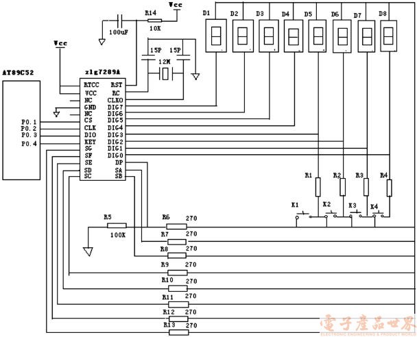
Abstract: This article introduces in detail the basic principles, features and original use of the digital tube and keyboard smart chip zlg7289A ...
Abstract: This article introduces the structure, function and interface characteristics of OMAP5910, and ...
Abstract: CS6208 is a chip specially developed by Myson Century for network control and transmission. It is based on 80 ...
'+ data.data.username +' '; dom + ='
Football Stadium Advertising Led Panels
Football Stadium Advertising Led Panels,Led Panel Display,Led Video Panel, Football Cup Led Display Billboards
Guangzhou Cheng Wen Photoelectric Technology Co., Ltd. , https://www.cwledwall.com