1 Introduction
With the increasing use of communication equipment and computer network devices, ensuring continuous power supply has become a critical requirement. In the past, shutting down power modules was not acceptable for such systems. Today, large power systems require flexible configurations, including redundant backups or load sharing. The ability to add or remove power modules without interrupting the system is essential. Hot-plugging technology addresses this challenge by enabling safe insertion and removal of power modules during operation.
2 Problems to Solve for Hot-Plugging
When inserting a power module into an active backplane, the input capacitance in the power circuit causes a surge current as the capacitor charges. This can lead to voltage glitches, potentially affecting other components, or even cause damage to the power supply. To enable hot-plugging, the key is to control the input current. A control FET is used to gradually increase the current from low to high, allowing the capacitor to charge safely. Once fully charged, the FET is fully turned on, and the circuit is powered directly from the external source.
3 Function Overview
The ISL6140 is a negative-voltage hot-swap controller from Intersil. It allows power modules to be safely inserted or removed from an operational backplane. The inrush current can be controlled by adjusting the gate voltage of an external N-channel FET. If the input voltage is outside the designed range, the switch turns off. A programmable electronic circuit breaker provides protection against short circuits. Additionally, the IC offers a signal output to indicate the status of the input voltage.
The ISL6140 features minimal external components and strong control capabilities, making it ideal for DC-DC pre-stage hot-swap applications and protection against overcurrent, overvoltage, and undervoltage conditions.
IC Features:
- Supports external negative N-channel FET
- Operating voltage range: -10V to -80V (-100V max) or +10V to +80V (+100V max)
- Adjustable inrush current limit
- Programmable overcurrent shutdown
- Programmable overvoltage protection
- Programmable undervoltage cutoff
- Voltage status indication
Application Areas:
- VOIP servers
- -48V telecom systems
- Negative voltage supply control
- +24V wireless base station power supplies
IC Pin Description and Internal Structure
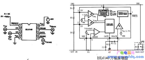
PIN1 PWRGD: Power status output
PIN2 OV: Overvoltage detection
PIN3 UV: Undervoltage detection
PIN4 VEE: Negative power supply connection
PIN5 SENSE: Current sensing input
PIN6 GATE: Gate drive output for N-channel FET
PIN7 DRAIN: Drain terminal of N-channel FET
PIN8 VDD: Positive power supply input
4 Peripheral Component Calculations
Calculating VUVL and VOVH:
VUVL and VOVH define the acceptable input voltage range. Within this range, the N-channel FET remains on, and the circuit operates normally. Outside this range, the FET turns off. These values are set using two operational amplifiers, and precision resistors (e.g., 1% metal film resistors) are recommended for R4, R5, and R6.
Formula:
VUV = 1.223 × (R4 + R5 + R6) / (R5 + R6)
VOV = 1.223 × (R4 + R5 + R6) / R6
Voltage waveform is shown below:
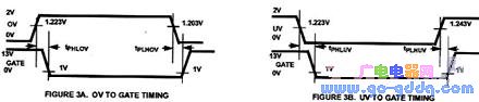
Tphlov: 0.6–3.0μs (Typical: 1.6μs)
Tplhov: 1.0–12.0μs (Typical: 7.8μs)
Tphluv: 0.6–3.0μs (Typical: 1.3μs)
Tplhuv: 1.0–12.0μs (Typical: 8.4μs)
5 N-Channel FET Selection
The N-channel FET is a critical component. Key parameters to consider include maximum input voltage (including transients), operating current, power dissipation, gate threshold voltage, and on-state resistance (RDSOn). The selected FET should provide sufficient margin and cost-effectiveness based on these factors.
6 Current Limit Resistor Selection (R1)
R1 is used for overcurrent detection. When more than 50mV is detected, the gate pin goes low, turning off the FET. The value of R1 can be calculated based on the desired overcurrent threshold:
R1 = 0.05V / Ioc
7 R2, C1, R3, C2 Parameter Selection
R2 can be chosen as 10Ω. R3 and C2 form a feedback network to control the inrush current.
I_inrush = (I_gate * CL) / C2
C2 = (45μA * CL) / I_inrush
C1 = (Vinmax - Vth) / Vth * (C2 + Cgd)
R3 = (Vinmax + ΔVgate) / 5mA (Typical: 18kΩ)
8 Power Signal Output Design
PWRGD is a power status output that indicates the input voltage status. It can be connected to an optocoupler or LED for visual indication.
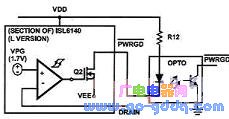
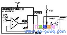
Optocoupler mode for soft start control; LED mode for intuitive voltage status display. If no external output is needed, leave the port floating.
9 Circuit Design Considerations
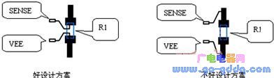
1. R1 Layout and Wiring
PCB layout significantly affects performance. Minimize interference and ensure wide traces to handle both normal and overcurrent conditions. Connect R1 directly to PIN4 (VEE) and PIN5 (SENSE), keeping traces short and close.
2. Suppressing Transient Overcurrent Pulses
To prevent transient pulses from triggering the power-off function, a filter can be added across R1. For pulses longer than 3μs, a low-pass filter with C3 and R7 (recommended 100Ω) is needed. The pulse width is determined by:
t = R*C*ln[1 - (V(t) - V(t0)) / (Vi - V(t0))]
Example: 1A normal current, 2.5A overcurrent, R1 = 20mΩ, 5A, 50μs pulse. Calculate C3 = 1μF.
Note: Choose FETs that can handle higher currents, as the RC filter only delays the effect, not limits the current.
3. OV and UV Application Notes
R4 should be much larger than R5 and R6. Set the sink current for OV and UV at ~100μA. Add a filter between UV and VEE or OV and UV to suppress transient noise.
4. Overvoltage Protection for the IC
The ISL6140 can withstand up to 100V. To protect it, add a surge absorber (e.g., DIODE’s SMAT70A) between VDD and VEE. Choose based on expected voltage variation, absorption capacity, and reverse pulse current rating.
6 Summary
As DC-DC modules become more widely used and demand for high-performance power supplies increases in communication networks, hot-swap control chips will continue to evolve. With fewer peripheral components, multiple protection functions, and good cost-performance, they are becoming essential in modern power systems.
Jiangsu Qilong Electronic Technology Co., Ltd. , https://www.qilongtouch.com