Consumer products, especially handheld devices, have recently seen significant improvements in complexity, like many other devices, such as turning off a single-slot battery, requiring a large voltage level, or requiring wall charging when the battery is charging. Type charger. The power supply on these devices must convert a single voltage level to provide different voltages for the processor, DSP, ASIC, SDRAM, flash drive, and LCD with LED backlighting. In addition, the voltage levels of the processors, DSPs, and FPGAs for different voltages must be as low as 1.2V and close to 0.9V, making the system more fault-tolerant and requiring a more accurate way to maintain these voltage levels. Within the specifications. In other particularly harsh situations, stacked white LED backlights require up to 30V and precise current control to deliver 10 white LEDs in sequence. For more complex cases, all of these devices must be turned on or off at different times due to reliability and battery life savings. If you fail to meet the above requirements, performance will immediately decrease, such as bus conflicts, shortened battery life or device occupancy will increase.
This article refers to the address: http://
Design challenges in mobile design and solutions enhance battery life, but must also be subject to system changes and performance enhancements. In order to meet these challenges, the current trend is towards
The program's diverse output DC-DC power management unit, with digital meta-control to allow for simple output voltage level software tailored, and power sequencing requirements. As system supply needs to change rapidly, a new "platform solution" can be changed to meet any type of system power supply needs to ease the designer's work. This can be achieved by specifying a power block that must be standardized across different application areas and digitally set to different requirements.
A number of different voltage DSP, FPGA, LED backlight and LCD display components, and other requirements built on handheld applications, will provide a digital programmable power management control function to meet Urgently demanding a large number of power supplies and providing devices for use on mobile equipment, as shown in (Figure 1).
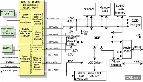
"Figure 1 typical handheld device power management system"
<Note: The typical handheld power management system can be fully set up due to power management. If the system block changes, the manager will change. There are eight voltage outputs in the figure, including three synchronous PWMã€buck〞 buck converters, a configurable PWMã€boost or buck〞 converter, three programmable PWMã€boost〞 boost or inversion Converter, a Low Dropout (LDO) linear rectifier, and a fully programmable Li-Ion battery charger. >
How to standardize a system without standards
When using some of the more complex handheld systems, such as portable media players, digital cameras/static cameras, smart PDAs/cameras or mobile phones, handheld GPS/PDAs, etc. use TFT LCDs and some current OLED screens, while also increasing The complexity of the power supply and the large number of different voltage requirements, sometimes even up to 12 different needs. Also, as the number of supply and demand increases, the order of supply becomes very important, because the accumulated input current requirements are particularly concentrated on turning all power supplies on or off, in addition to the power consumption and associated temperature rise, causing tightening at lower voltages. The reduced accuracy of the power supply is the most important reason for the difficulty in improving maintenance reliability. All of the above are required to address new platform design issues with shorter development times, cheaper products, and improved reliability to provide new solutions. Therefore, the advantage of standardizing system power management is that the power link and monitoring functions are the same across platforms.

Figure 2 Power Management Block Diagram shows the different power supplies and configurations possible on different handheld devices such as PDAs, smart phones or DSCs. 》
To aid in standardization, a digital programmable supply platform must have an analog controller/converter to provide better advantages than a fixed solution and pure digital element PWM control. One of the advantages is that programmable solutions drastically reduce the risk of changing system requirements, which can be modified by the programmable ordering order, while sorting channels can also be replaced by tracking channels by simplifying the programmatic controller. This minimizes the possibility that the board needs to be replaced due to system requirements. This programmable solution also gives designers greater confidence that the board will be successful in one design. If problems are encountered, reprogramming can solve these problems and debug and test the functions of the board. On a company-wide basis, programming solutions are also allowed to go beyond platform applications, ie existing designs can be re-used as separate solutions after simple reprogramming. Analog PWM converters and LDOs allow for a comparison Small, simple, and inexpensive devices, with a complete DSP on the chip.

Figure 3 shows the detailed architecture of the LED driver, up to 10 LEDs can be connected in sequence; and programmatic brightness control through the I2C bus. 》
Analog processing also allows the MOSFETS power supply to be integrated where appropriate, while the PWM can be operated at different programmed frequencies to reduce the size of external components. If designed in this way, the DSP requires a very high clock and associated high-resolution AD converter to improve accuracy, and the digital meta-method also suffers from problems related to quantization errors, a fully programmed power supply. The device features an integrated, non-volatile (NV) load-balanced analog PWM controller to provide power management requirements on any power system. This programming capability allows high performance analog signals to be 0.5% accurate in processing and temperature, and a standard digital CMOS process with non-volatile analog load balancing on a basic, lower cost component. Standardization is easy to achieve through NV programmatic/reprogrammed resiliency and configurable hardware functions, as well as the ability to programmatically simulate analog parameters to systems and GUI development tools using a digital interface. It is an analog function that highly integrates the power supply and is regulated using programmable power control.
Complete flexibility, a range of devices with a fully programmed power supply and integrated PWM controllers for monitoring, differential and decrement sequencing to provide all the power management needs needed in a handheld power system. A range of devices can be set up on five or more channels, and the battery charger functions to meet most needs. A possible option is shown in Figure (Figure 2). The system can be set to have 5 voltage outputs plus reference values, including: configurable synchronous PWM “buck†buck converter, PWM “boost†boost converter, PWM “buck-boost†negative DC -DC converters, and LDOs exhibit an overall accuracy of ±0.5% and are flexible to design any system configuration. An IC two-wire series bus can be used to program voltage levels and monitor status.
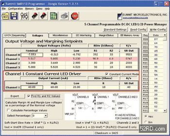
Figure 4 Graphical User Interface
<Note: Non-variable programming features are very easy to access to the graphical user interface (GUI) to assist in the modification of the output voltage and current within the system. All voltage levels and fault triggers can be programmed using the window GUI, and a PC-compatible parallel port to I2C or USB serial bus programming. The critical high and low values ​​can be programmed in advance and a simple I2C command will be used. Propose and reduce LED brightness. >
The power system can be used to turn on/off the descending order, and each channel can be assigned to one of these four sequential positions. The power supply can also be turned on/off separately by I2C command, or by the insertion of an active slot. The descending order is different from the time-based ordering, using feedback to determine that each output before the next channel is enabled is valid.
Each output voltage and battery monitors for low voltage and high voltage conditions. When a fault occurs, all power supplies may shut down or immediately deactivate multiple output status latches for use as a monitoring circuit to notify the host processor or other system errors, and a low voltage lockout (UVLO) circuit ensures IC The UVLO function exhibits hysteresis when the battery voltage is not activated before the safe operating voltage is reached, ensuring that noise on the power supply rack does not inadvertently cause system malfunction.
When a low voltage or high voltage condition occurs similar to a monitoring output or a low voltage error in the system power supply, all monitored power supplies may provoke an internal error response such as a sequencing power down operation, or a Immediately forced to close.
Each power supply output will also be individually powered from the main system battery at any point via an I2C command, and the battery voltage will be continuously monitored to maintain a low voltage state. When a programmed threat level is reached, the POWER-FAIL pin (SMB112) is inserted and latched.
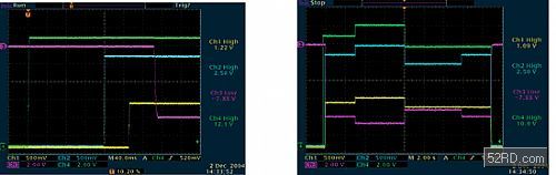
"Figure 5 power-activated series sequencing and critical high/low waveform of SMB 110"
<Note: Note: The supply channel starts the nominal voltage in series order, then the critical high or low value, then the stream sequencing is closed, and channels 1, 2, 3, and 4 are the first critical high value, and Channels 2 and 3 are then critical low values. Up to 4 PWM power supplies can be controlled. >
Dynamic voltage control
Critical or dynamic voltage control establishes three pre-programmed settings that allow each channel to set voltage or current changes through an I2C command, all of which can critically exceed the same programmable range that each channel can achieve. When using a channel set to the LED driver (Figure 3), the threshold is an ideal way to provide three different brightness settings. Due to the flexibility of the part, the LEDs can be sequenced to provide brightness uniformity or in parallel settings to provide different brightness control. In the example shown below, up to 10 LEDs can be driven by an increased benefit channel. When set to a fixed current LED driver, the boost efficiency output will automatically servo the output voltage, so the current flowing through the LED link will be the same as the current flowing through the resistor attached to the COMP 1 pin. The following LED current can be driven. Ten white LEDs with maximum current, approximately 30 mA due to LED limitations. In addition, the rate of rotation of each output is limited by the digital software activation circuitry, which can be programmed by the user without the need for an external capacitor. All programmable settings are stored in a non-identifiable lander and are easily accessible and modified.
Dynamic voltage control is essentially a power critical application and has a very dynamic operating mode. In this example, high power components can be supplied from different voltage levels and maintained under certain conditions, thus significantly extending battery life significantly.

"Figure 6 Programmable Linear Li-Ion Battery Charger"
<Note: A programmable linear Li-Ion battery charger and a variety of charging cycles are included. The register contains all the information about the battery charging algorithm. Here are the programming options, like the last floating voltage. , charge current, pre-charge current, fast charge voltage, fast charge current, float voltage (0.5%), termination charge current, OT/UT threshold, and charge timer. >
battery charger
Li-Ion battery chargers require three charging modes for optimum performance and safety. These modes of operation include a limited current precharge mode for use when the battery is very severely discharged, a fast charge high current mode, and a fixed voltage slowly charge mode, as shown in Figure 6. When a lithium-ion battery is severely discharged, battery charging should begin with a limited battery charging current. After the pre-charge floating voltage is exceeded, the battery charging current should be increased from the pre-charging current to the fast charging current. The fast charge current should also be programmed, and the final float voltage should be able to comply with the new and higher capacity Li-Ion battery with a larger floating voltage.
Once the last floating voltage is exceeded, the battery charger should be able to choose to enter a fixed voltage mode while its battery voltage remains fixed to allow the charging current to gradually decrease. The fixed voltage charging mode should continue until the charging current drops below the termination current threshold. A programmable termination current rating is very useful because it allows the system to make decisions on frequent charging to supply higher battery capacity or to reduce charging time.
Temperature detection input is also required to avoid excessive battery temperatures during charging. The temperature monitoring circuit should meet all of the different internal resistances and cancel battery charging until the battery voltage drops to within safe operating range. 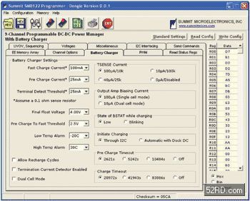
Figure 7 Programmable Battery Charger Options
in conclusion
New digital programmatic power supply provides I2C programmed output voltage, turn-on and turn-off sequencing, individual power supply enable control, battery monitoring and charging, UV and OV monitoring at PWM output, critical LED backlight level, spin rate control, and programmatic Power on and off sorting and other functions. Actively control the DC output voltage level to within 0.5% of the low and high value lines to meet the stringent debug requirements of high performance components, and further extend the operational reliability, critical power supply test system performance goals and provide An easier way to make adjustments like brightness and capacity. The integration of active precision control, programmatic features and pre-set flexibility allow system designers to create a “platform solution†that can be easily modified via software without major hardware changes. In addition, combined with reprogramming capabilities, it will help accelerate the design cycle and spread from a basic design to a new generation of product lines in the future.
Cassava Dregs Separator,Cassava Processing Machine,Cassava Processing Equipment,Cassava Milling Machine
Hunan Furui Mechanical and Electrical Equipment Manufacturing Co., Ltd. , http://www.frcornthresher.com