Abstract: This applicaTIon note shows an example of how to interface a Phantom Real-TIme Clock (RTC) to a microcontroller. This note includes a schemaTIc and example code.
Pin Assignment DescripTIonThe Phantom clocks and SmartWatch sockets provide battery-backed NV SRAM or NV SRAM control, respectively, and add timekeeping information. The timekeeping data is accessed without using any of the SRAM data space. Access of the timekeeping data is accomplished by writing a unique 64 -bit sequence to the controller. The controller then inhibits access to the SRAM for the next 64 reads or writes. In this example, a DS1216C, DS1216E, DS1243Y, or DS1244Y is connected to a DS2250. The DS2250 microcontroller is compatible with the industry standard 8051 architecture. Larger densities could be supported by using bank-switching techniques. Some memory expansion techniques are discussed in Application Note 81, "Memory Expansion with the High-Speed ​​Microcontroller Family."
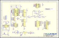
A SmartWatch / Phantom Clock schematic of the circuit is shown in Figure 1. Software is shown in DS1216 / DS1244 Code.
More Detailed Image
Figure 1. SmartWatch / Phantom Clock schematic of the circuit.
DS1216 / DS1244 Code / ********************************************* *************************** / / * ds1216an.c-access DS1216 or DS1244 using Phantomdemo circuit * / / ****** ************************************************** **************** / / * For SmartWatch / ROM sockets, input D (input) is connected to A0, * / / * the Q (output) is connected to D7 (data bit 7 of the data bus) and * / / * / WE connected to A2. On the SmartWatch / RAM sockets, DQ is connected * / / * to D0, and / WE is connected to / WR. For both, / OE is connected to * / / * / RD and / CE is connected to A15. Access requires use of XBYTE * / / * function. All other SRAM / ROM address and Data pins are connected to * / / * their respective processor pins. The example is intended to show * / / * how to access the clock only. Not all memory configurations will * / / * work with this setup. Note that SmartWatch sockets must be mapped * / / * to data, not program memory space. Program memory fetches would * / / * interrupt the access protocol sequence. If / RST is connected to an * / / * address, the / RST bit must always be written to a 1. Otherwise, * / / * access to the clock will be lost. This program is for example only * / / * is not supported by Dallas Semiconductor MAXIM * / / *********************************************** ***************************** / #include / * Prototypes for I / O functions * / #include / * Register declarations for DS5000 * / #include / * needed to define xdata addresses * / / ************************* bit definitions ************* ***************** / / ***************************** Defines * ********************************* / / *************** ********** Global Variables ***************************** / uchar mode = 0, yr = 0x01 , mn = 0x03, dt = 0x30, dy = 0x26, hr = 0x14, min = 0x15, sec = 0x16; #define RDADDR XBYTE [0x0000] / * I / O is on D0 for SmartWatch / RAM * / #define WRADDR XBYTE [0x0000] #define RDADDRROM XBYTE [0x0004] / * / WE is on A2 for SmartWatch / ROM * / #define WR1ADDR XBYTE [0x0001] / * D (data input) on A0 for / ROM * / #define WR0ADDR XBYTE [0x0000 ] / *********************** Function Prototypes *********************** ***** / void ds1216_wr (); void ds1216_rd (); void test (); void ds1216_close (); void ds1216_open (); void entry (); uchar rbyte (); void wbyte (uchar); void ds1216_open ( ) / * ----- send open protocol to RTC on 1216 ------- * / {uchar a = 0xc5, inc; ds1216_close (); for (inc = 0; inc <4; inc ++) {wbyte (a); / * send out the pattern b yte * / a = a ^ 0xff; / * generate next pattern byte * / wbyte (a); / * send out the pattern byte * / a = (a >> 4) | (a << 4); / * generate next pattern byte * /} / * repeat until 8 bytes sent * /} void ds1216_close () / * ----- make sure clock is not in access mode ----- * / {uchar i; / * read from the part at least 64 times to make sure * / for (i = 0; i <9; i ++) / * the clock is not being accessed * / {rbyte ();}} uchar rbyte () / * ---- -read one byte from the clock and return ------- * / {uchar savbyte = 0, getbyte; uchar i; for (i = 0; i <8; i ++) {if (mode) / * ROM : / WE is on A2, and must be high to read * / {getbyte = RDADDRROM & 1; / * data bit output (Q) is in D0 * /} else / * RAM: / WE is on / WR (DS5000) * / {getbyte = RDADDR & 1; / * DQ is D0 * /} getbyte << = i; / * make room for the data bit * / savbyte | = getbyte; / * and save it * /} return savbyte;} void wbyte (uchar dat) / * ------------------------------------------ --- * / {/ * This routine writes eight serial bits to the part * / int inc, x; for (inc = 0; inc <8; inc ++) {if (mode) / * ROM: / WE (A2) / CE and / OE toggle low to write * / {if (dat & 0x01) / * data bit input (D ) is in A0 * / x = WR1ADDR; / * A0 (D) is high, A2 (WE) and OE are low * / else x = WR0ADDR; / * A0 (D) is low, A2 (WE) and OE are low * / dat >> = 1;} else / * RAM: / WE and / CE toggle low to write * / {WRADDR = (dat & 1); / * write DQ0 * / dat >> = 1;}}} void ds1216_rd () / * -------- read RTC on 1216 ---------- * / {int inc; ds1216_close (); / * make sure RTC is not already in access mode * / ds1216_open (); / * now send the protocol to open the RTC * / printf (""); for (inc = 0; inc <8; inc ++) {printf ("% bx", rbyte ());} printf ("");} void ds1216_wr () / * -------- write time / date info to 1216 RTC ------ * / {ds1216_close (); / * make sure RTC is not already in access mode * / ds1216_open (); / * now send the protocol to open the RTC * / wbyte (0); / * 100th seconds * / wbyte (sec); / * seconds * / wbyte (min); / * minutes * / wbyte (hr); / * hrs * / wbyte (dy); / * day * / wbyte (dt); / * date * / wbyte (mn); / * month * / wbyte (yr); / * year * /} void entry () / * -------- time / date info to load into the clock ----- -* / {printf ("Enter the year (0-99):"); scanf ("% bx", & yr); printf ("Enter the month (1-12):"); scanf ("% bx ", & mn); printf (" Enter the date (1-31): "); scanf ("% bx ", & dt); printf (" Enter the day (1-7): "); scanf ("% bx ", & dy); dy = dy | 0x10; / * make sure _RST bit is high * / printf (" Enter the hour (1-24): "); scanf ("% bx ", & hr); / * hr = hr & 0x3f; / * force clock to 24 hour mode * / printf ("Enter the minute (0-59):"); scanf ("% bx", & min); printf ("Enter the second (0-59) : "); scanf ("% bx ", & sec);} void test () / * ------- loop read and display once per second ------- * / {int prv_sec = 0x99, inc; while (! RI) / * Read & Display Clock Registers * / {ds1216_close (); ds1216_open (); rbyte (); / * throw away fractional seconds * / sec = rbyte (); / * get the time from RTC on DS2250t * / min = rbyte (); hr = rbyte (); dy = rbyte (); dt = rbyte (); mn = rbyte (); yr = rbyte (); if (sec! = prv_sec) / * di splay every time seconds change * / {printf ("Yr Mon Dte Day Hr: Mn: Sec"); printf ("% 02.bX% 02.bX% 02.bX% 02.bX", yr, mn, dt, dy); printf ("% 02.bX:% 02.bX:% 02.bX", hr, min, sec);} prv_sec = sec;} RI = 0; / * Swallow keypress to exit loop * / int main (void) / * --------------------------------------------- ---------- * / {uchar M; / * on entry, the clock could be open for access. This could happen if power goes away right after the 64-bit pattern match is complete. On power up , the next 64 bits would be directed to the clock instead of RAM. To keep from writing garbage to the clock, the first 64 RAM accesses should be reads. * / ds1216_close (); / * make sure that we are not already in the clock * / while (1) {printf ("DS1216 Demo build 109 Mode ="); if (mode) printf ("ROM"); else printf ("RAM"); printf ("(T) oggle RAM / ROM mode (I) nit clock (R) ead clock (L) oop read "); printf (": "); M = _getkey (); printf ("% c ", M); switch (M) {case 'I' : case 'i': entry (); ds1216_wr (); break; case 'L': case 'l': test (); bre ak; case 'R': case 'r': ds1216_rd (); break; case 'T': case 't': printf ("1 = ROM, 0 = RAM:"); scanf ("% bx", & mode ); break;}}}
Pin Assignment
DescripTIonThe Phantom clocks and SmartWatch sockets provide battery-backed NV SRAM or NV SRAM control, respectively, and add timekeeping information. The timekeeping data is accessed without using any of the SRAM data space. Access of the timekeeping data is accomplished by writing a unique 64 -bit sequence to the controller. The controller then inhibits access to the SRAM for the next 64 reads or writes. In this example, a DS1216C, DS1216E, DS1243Y, or DS1244Y is connected to a DS2250. The DS2250 microcontroller is compatible with the industry standard 8051 architecture. Larger densities could be supported by using bank-switching techniques. Some memory expansion techniques are discussed in Application Note 81, "Memory Expansion with the High-Speed ​​Microcontroller Family." A SmartWatch / Phantom Clock schematic of the circuit is shown in Figure 1. Software is shown in DS1216 / DS1244 Code.
More Detailed Image
Figure 1. SmartWatch / Phantom Clock schematic of the circuit.
DS1216 / DS1244 Code / ********************************************* *************************** / / * ds1216an.c-access DS1216 or DS1244 using Phantomdemo circuit * / / ****** ************************************************** **************** / / * For SmartWatch / ROM sockets, input D (input) is connected to A0, * / / * the Q (output) is connected to D7 (data bit 7 of the data bus) and * / / * / WE connected to A2. On the SmartWatch / RAM sockets, DQ is connected * / / * to D0, and / WE is connected to / WR. For both, / OE is connected to * / / * / RD and / CE is connected to A15. Access requires use of XBYTE * / / * function. All other SRAM / ROM address and Data pins are connected to * / / * their respective processor pins. The example is intended to show * / / * how to access the clock only. Not all memory configurations will * / / * work with this setup. Note that SmartWatch sockets must be mapped * / / * to data, not program memory space. Program memory fetches would * / / * interrupt the access protocol sequence. If / RST is connected to an * / / * address, the / RST bit must always be written to a 1. Otherwise, * / / * access to the clock will be lost. This program is for example only * / / * is not supported by Dallas Semiconductor MAXIM * / / *********************************************** ***************************** / #include
As users hands or debris enter the zone 6 inches (15cm) from the infrared sensor on top of the dustbin, the lid will automatically open
Rectangular Sensor Automatic Dustbin
Rectangular Sensor Automatic Dustbin
NINGBO ZIXING ELECTRONIC CO.,LTD. , https://www.zixingautobin.com