Design of Truck Voice Alarm Based on CAN Communication
Automobile diagnosis technology is an indispensable part of automobile safety technology. It can promptly give a voice alarm when a car breaks down to avoid accidents. CAN stands for Controller Area Network and is one of the most widely used fieldbuses in the world. Because of the excellent characteristics of CAN bus technology, it is widely used in automotive electrical systems and other real-time control units. A communication network based on CAN bus has the advantages of high speed, strong noise resistance and good versatility.
The truck voice alarm system based on CAN bus technology we designed can provide a safe driving environment for car occupants. The voice alarm system uses Motorola's M68HC908GZ16 microcontroller. The microcontroller has a small size, complete resources, and a high cost performance.
CAN bus bit timing
The CAN bus adopts synchronous serial communication mode, and the characters in the data stream are synchronized between characters, and the bits within the characters are synchronized. This requires that the sending and receiving parties must control the sending and receiving of data with a synchronized clock. To maintain bit synchronization in a fairly long data stream, the receiving end must be able to identify when each binary bit starts, which is the bit timing. Usually, in order to ensure that the receiver clock and the transmitter clock are strictly consistent, the receiver uses the demodulator to extract the synchronization signal from the data stream, or the receiver and the transmitter use a unified clock. But even so, it is still difficult to solve the problem of bus transmission delay. In response to the above problems, the bit timing of the CAN bus has improved bit encoding / decoding.
The CAN bus bit timing consists of 4 parts: synchronization section (SYNC_SEG), propagation section (PROP_SEG), phase section 1 (PHASE_SEG1) and phase section 2 (PHASE_SEG2). The synchronization section is used to synchronize the nodes on the bus, waiting for a jump edge in this section; the propagation section is used to compensate for the physical delay time in the network; phase section 1 and phase section 2 are used to compensate for phase errors. Read the bus level at the sampling point.
The M68HC908GZ16 microcontroller (see Figure 1) has a built-in CAN controller that provides a baud rate control register; SJW (Resynchronization Jump Width) determines the time quantum during which a bit time is extended or shortened during a resynchronization; BRP is Baud rate prescaler coefficient; Spl (sampling mode bit) determines the number of valid bit samples.
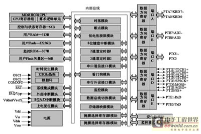
Figure 1 MC68HC908GZ16 internal structure
Bit timing is mainly used to define the rate of CAN bus communication. The same communication rate should be defined for each node on the same bus, otherwise the communication cannot be made. The calculation formula of the bus working frequency of the CAN controller is as follows:

Where: BRP is the system prescaler factor, and its value in the TSEG1 field is 0 to 63; the values ​​of TSEG1 and TSEG2 are determined by the bit timing register programming, and satisfy 1≤TSEG1≤7, 2≤TSEG2≤15 . The setting of the bit timing of the alarm device defines the communication frequency as 250KB / s. Set DSC = "BRP" = 1, TSEG1 + TSEG2 = 5, the system crystal frequency is 8MHz, that is XTAL = 8MHz, CAN communication frequency is calculated by the above formula to get 250KB / s.
The final bit timing setting result is: BRP = 1, TSEG2 = 2, TSEG1 = 3.
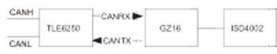
Figure 2 Voice alarm system structure
Design overview
The design goals of the truck voice alarm system are: low cost; powerful functions; suitable for daily applications; can be applied to various vehicles. The system can realize the following functions: use the CAN network to receive the fault code of the truck; second, obtain the corresponding voice prompt by identifying the signal transmitted by the CAN system and processing the signal, and realize the corresponding fault by connecting with the voice chip Voice playback alarm.
The voice alarm system is based on Motorola's MC68HC908GZ16 processor, and uses its rich interfaces to expand the use of peripheral modules such as voice playback and CAN communication interface to make the product design more user-friendly. The MC68HC908GZ16 processor has the following advantages:
1. Rich hardware resources
MC68HC908GZ16 is a flash memory MCU, which has 16K of FLASH storage space and 1K of RAM storage space. There is a phase-locked loop circuit inside, which can make the bus frequency up to 8MHz when using a low-speed crystal oscillator. At the same time, it has up to 37 general-purpose I / O ports, which can be easily connected with other peripheral devices.
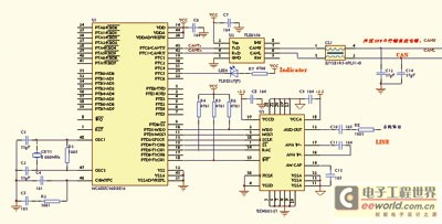
Figure 3 Schematic diagram of the truck alarm circuit
2. Strong anti-interference ability
The internal CAN controller is integrated, and CAN communication has the characteristics of strong anti-interference, which ensures that the product can operate efficiently and stably under harsh environmental conditions.
This design uses CAN communication to complete the design of the truck voice alarm system. The system structure is shown in Figure 2.
Data communication is realized through the MSCAN08 module integrated on the MC68HC908GZ16. Using the I / O port of C68HC908GZ16, we used the ISD4002-120 digital voice chip that is common on the market in the design. The chip uses 3V DC power supply, can record and save 2min voice information. The sampling frequency is 8kHz, and the information resolution can reach 200ms, which can reproduce voice, music, tone and effect sound very realistically.
hardware design
It can be seen from Figure 3 that the truck alarm circuit is mainly composed of three parts: the microcontroller MC68HC908GZ16 (internal integrated MSCAN08 module), the voice chip ISD4002 and the CAN bus transceiver TLE6250, ZJYS. The microcontroller is responsible for the initialization of the MSCAN08 module, and realizes communication tasks such as data reception and transmission through the CAN module. The CAN communication control module mainly completes the CAN communication protocol. The CAN control module can complete all functions of the physical layer and the data link layer, and is suitable for automobiles and general industrial environments. Using CAN communication can not only reduce the wire connection, but also enhance the diagnosis and monitoring capabilities.
The CAN transceiver TLE6250 is used to provide the driving capability for differential transmission and reception of the bus. It has the best matching of the output signals CANH and CANL, lower electromagnetic radiation, and no standby mode. Two small 25PF capacitors are connected in parallel between CANH and CANL and ground, which can filter out high frequency interference on the bus and prevent electromagnetic radiation.
Software description
The software programming mainly realizes two major functions: use the bus to receive the fault code; realize the corresponding voice fault alarm by converting the fault code. Voice playback is designed according to its function. Most operations of the entire program are completed in the main program, and CAN reception is completed in the interrupt.
The operation in the main program is to initialize each register and I / O port, and then perform corresponding processing according to the flag bit in an infinite loop. The specific process is shown in Figure 4.

Figure 4 main program flow chart
1. Voice module software design
The voice module uses the ISD4002 chip. The single chip microcomputer establishes a connection with the ISD4002 through the I / O interface, and controls the address of the voice playback through the command word to realize the control of the voice playback.
2. CAN communication module software design
When programming on the CAN bus, a series of control word configurations need to be defined and configured on the device. The specific steps include: defining CAN control register, defining bit timing, defining information body shielding method, information body initialization, information body sending data and information body receiving data.
(1) Initialization of MSCAN08 module
The initialization of the MSCAN08 module is mainly to define the communication rate. Configure the bit timing register to determine the CAN communication rate, configure the global mask register to determine the filtering strategy, and initialize each message body. To initialize the information body, you need to determine the type of information body (send or receive), and set the ID, SRR, IDE, and RTR that comply with the CAN protocol. CAN communication must be initialized first. After the initialization of the MSCAN08 module is completed, the MSCAN08 module can return to the working state and perform normal communication tasks.
(2) Data receiving and sending
The sending of the message is independently completed by the CAN controller. The microcontroller only needs to transmit the sent data to the corresponding sending information body of the sending MSCAN08 module, and then set the "send request" flag in the command register. The flow chart of message sending is shown in Figure 5, and make a judgment before sending. The sending procedure is divided into sending remote frames and data frames. The remote frame has no data field, and its program flow chart is shown in Figure 5 (left).
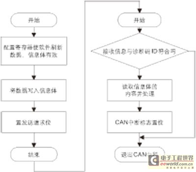
Figure 5 CAN sending and receiving flow chart (the left is the sending process, the right is the receiving process)
The reception of the MSCAN08 module is very flexible. If the meaning of ID is specified according to the CAN bus application layer protocol, you can receive the required data into the message buffer by setting 3 mask registers (1 global, 2 special), and filter out the unnecessary Then read the ID of the current message buffer to determine the meaning of the data. There are two main ways to receive AN82527 messages: interrupt mode and query mode. Interrupt mode is adopted in this system. The flow chart of message reception is shown in Figure 5 (right).
summary
The truck voice alarm system has been tested on the bench, and has achieved good communication effects in the bench test with other controllers, and can achieve a good voice alarm function. In addition, the design needs to be further verified by the actual car, and its basic design ideas can also be applied to cars.
Flexible LED strips are assembled using FPCB and assembled with patch LEDs. Because the FPC material is soft, it can be bent, folded, and wound freely. It can be moved and stretched and folded in three-dimensional space. It is suitable for irregular places and small spaces, and it can be bent and wound at will. It is suitable for arbitrarily combining various patterns in decorations such as advertisements. It is DC 5-24V power supply, low power consumption, silicone potting, bright color, uniform color mixing, not easy to damage, beautiful appearance, safe and reliable, easy to install
Flexible LED Strip,S Shape LED Strip,5050Smd Flex LED ,Flex LED Strip
SHEN ZHEN SEL LIGHTING CO.,LTD , https://www.sel-lighting.com