Generally, it can be solved by using a diode in the positive pole of the power supply. However, due to the voltage drop of the diode, it will cause unnecessary loss to the circuit. Especially in the case of battery power supply, the battery voltage is 3.7V, and you use the diode to drop 0.6. V, so that the battery life is greatly reduced.
MOS tube anti-reverse connection, the advantage is that the pressure drop is small, small enough to be negligible. The current MOS tube can achieve an internal resistance of a few milliohms, assuming 6.5 milliohms, passing a current of 1A (this current is already large), and the voltage drop across it is only 6.5 millivolts.
As MOS tubes become cheaper and cheaper, people are gradually starting to use MOS tubes to prevent reverse power connections.
NMOS tube prevents power reverse circuit:
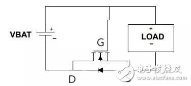
When connected correctly: just after power-on, the parasitic diode of the MOS transistor is turned on, so the potential of S is about 0.6V, and the potential of G is VBAT, VBAT-0.6V is greater than the threshold voltage of UGS, DS of MOS tube It will turn on. Because the internal resistance is small, the parasitic diode is short-circuited and the voltage drop is almost zero.
When the power supply is reversed: UGS=0, the MOS tube will not be turned on, and the circuit of the load is broken, thus ensuring circuit safety.
PMOS tube prevents power supply reverse circuit:
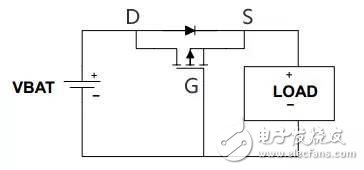
When properly connected: just after power-on, the parasitic diode of the MOS transistor is turned on, and the power supply and the load form a loop, so the S pole potential is VBAT-0.6V, and the G pole potential is 0V, the PMOS transistor is turned on, and the current flowing from D to S Short the diode.
When the power supply is reversed: the G pole is high and the PMOS transistor is not conducting. Protect the circuit.
Connection skills
The NMOS transistor DS is connected to the negative pole, and the PMOS transistor DS is connected to the positive pole, so that the parasitic diode direction is oriented toward the current direction of the correct connection.
Feeling that the DS flow is "reverse"?
Careful friends will find that the current flow of DS in the anti-reverse circuit is opposite to the current direction we usually use.
Why do you want to be countered?
Utilizing the conduction of the parasitic diode, UGS meets the threshold requirement just after power-on.
Why can it be reversed?
In the case of a triode, the current direction of the NPN can only be C to E, and the current direction of the PNP can only be E to C. However, the D and S of the MOS tube are interchangeable. This is also one of the differences between the triode and the MOS tube. (On this issue, let's open another article to discuss, this only discusses the anti-reverse effect of MOS tubes).
The above is a schematic diagram. In practical applications, a resistor should be added to the front of the G pole.
Multi-Layer Circuit boards. In order to increase the area that can be wired, the multilayer board uses more single or double-sided wiring boards. Using a double-sided inner layer and two single-sided outer layers, the printed circuit board which is alternately arranged by the positioning system and the insulating bonding material and the conductive pattern is interconnected according to design requirements becomes four layers, similiar stack up for 6 layer, 8 layers etc. The layers are more than two called multiple layers printed circuit board. The number of layers of the board does not mean that there are several layers of independent wiring layers. In special cases, empty layers are added to control the thickness of the board. Usually the number of layers is even and the outermost two layers are included.
Multilayer Pcb,Multilayer Printed Pcb,Multilayer Printed Circuit Board ,Multi-Layer Circuit Board
Chuangying Electronics Co.,Ltd , https://www.cwpcb.com