Abstract: This paper introduces a parking lot vehicle detection system based on SPCE061A type MCU. The system uses the ground sense coil to detect the vehicles entering and leaving the parking lot, controls the automatic movement of the brake lever machine, and has the parking space display and voice prompt function. The system cooperates with the IC card and the image monitoring and processing device to form a complete intelligent parking system, thereby realizing intelligent management of the large parking lot. The paper introduces the design principle of the vehicle detection part, and gives the corresponding hardware interface circuit and software programming points.
This article refers to the address: http://
1 Introduction
In the modern large-scale parking lot, the intelligent parking management system makes the vehicle entry and exit procedures simple and safe, and realizes the functions of automatic detection, billing, statistics and display of the vehicle, which greatly saves human resources and improves work efficiency. In the entire parking management system, the vehicle detection part is the key to the system. This design introduces a parking lot vehicle detection system, which realizes the control of the brake lever machine and the parking space prompting function through the vehicle detector distributed in the entrance and exit.
2 system overview
The schematic diagram of the entire parking management system is shown in Figure 1. The information display card is an LED display that displays the current time and parking space information. When a car enters, the driver swipes the card, the card swipe signal is read in by the controller, the control gate machine is lifted, the voice prompts “Welcomeâ€, the local sense coil detects the vehicle entering, updates the parking space information, captures the vehicle picture, brake The rod machine falls; likewise, when the vehicle drives out, the driver swipes the card, and the control gate machine lifts up. The voice prompts “Thank you for visiting, the local sense coil detects the vehicle leaving, captures the vehicle information, the brake rod falls and updates the parking space information. The processing of image information and IC card data information will be completed by the upper computer of the duty room.
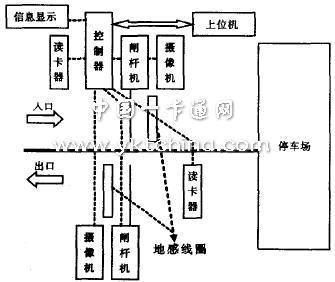
Figure 1 Schematic diagram of the parking management system
The controller design block diagram is shown in Figure 2. The system selects SPCE061A type MCU as the main control chip, and the MCU detects the arrival of the vehicle by reading the card signal and the level change of the phase-locked loop circuit. The DS1302 clock circuit provides accurate time information for the system. It displays the parking space and time information in real time by driving the LED display card. The system has a serial communication communication interface with the host computer.
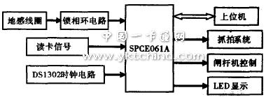
Figure 2 Overall design block diagram of the intelligent parking lot vehicle detection system
3 system principle introduction
3.1 Vehicle detection section
Accurate detection of the vehicle is a prerequisite for the normal operation of the system. Through various scheme comparisons, the vehicle detector of the present design adopts a ground-sensing coil detection scheme. The ground sense coil vehicle detector is a vehicle detector based on the principle of electromagnetic induction. The ground-sensing coil Ll is buried under the road surface, and a toroidal coil with a certain working current is wound by a multi-turned wire and buried in the road. The coupling circuit composed of the ground coil is shown in Figure 3:
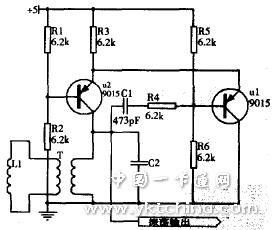
Figure 3 coupled oscillator circuit
T is an isolation transformer with a turns ratio of 1:1. The transistors U1 and U2 form a common emitter oscillator. The resistor R3 is the common emitter resistance of the two transistors and constitutes a positive feedback. The ground sense coil acts as an inductive component in the detector resonant circuit and forms an LC resonance with the oscillator circuit of the vehicle detector. When a vehicle passes, it will increase the magnetic flux generated by the unit current in the coil, resulting in a slight change in the inductance value of the coil, thereby changing the frequency of the LC resonance. This frequency change is used as an input signal for the car passing through the inductive coil. In order to detect this change, a common method is to determine whether the car arrives by calculating the number of oscillation pulses per unit time by the single chip microcomputer. In this design, it is necessary to detect the frequency variation of the two ground-sensing coils. If the amount of change of the two-channel signal frequency is measured by the single-chip microcomputer at the same time, the system is relatively large, and the program is relatively complicated, so that the burden of the single-chip microcomputer is heavy. Here is a new detection method: the frequency change is detected by the phase-locked loop audio decoder LM567. The application circuit diagram is shown in Figure 4:
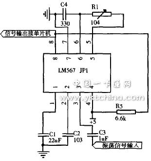
Figure 4 phase-locked loop circuit
The external resistors and capacitors of pins 5 and 6 of the LM567 determine the center frequency of the IC's internal voltage controlled oscillator, fo=1/1.1RC. The first and second feet are usually shown in Figure 4. The phase-locked loop circuit is connected to the ground capacitor to form an output filter network and a loop low-pass filter network. The capacitance of the second pin determines the capture bandwidth of the phase-locked loop circuit. The value can be calculated using this formula:
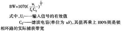
When the audio decoder LM567 is working, if the input signal frequency falls within a given passband, the phase-locked loop will lock this signal, and the internal transistor of the LM567 is controlled to be turned on, and the 8-pin output is low, otherwise the output is output. High level. When the input signal frequency is in the passband, the LM567 is locked and the output is low. Usually, in the absence of a car, the oscillation frequency of the coupling circuit will remain constant within a certain range. When the car passes through the ground-sensing coil, the oscillation frequency of the coupling circuit changes, and, depending on the model, and the iron of the car itself. The quality is uneven, so that the change of this frequency also floats within a certain range. Therefore, through experiments, select the appropriate LM567 capture bandwidth value, so that when there is no car, the input signal frequency has a slight change, but this floating frequency is in the passband, LM567 lock, 8 pin output low level; When the car arrives, the frequency changes drastically in the passband, and the 8-pin will output a high level. At this time, the detection of the arrival of the vehicle is converted into the detection of the level, and the arrival of the vehicle can be sensed by triggering the external interruption of the single-chip microcomputer, without complicated procedures to distinguish whether the frequency change at this time is from the arrival of the vehicle. Caused, greatly reducing the difficulty of programming.
3.2 Other control parts
The control of the gate machine is to control the forward and reverse of the DC motor of the gate machine. The output of the high-low level relay is operated by the control port of the single-chip microcomputer. The positive and negative voltages can be realized by adding positive and negative voltages to the motor of the DC motor. For the time record, the DS1302 calendar chip is used here. The DS1302 can record the year, month, day, week, hour, minute and second. It can be connected to the backup power supply and can always keep working continuously when the main power is off. The single-chip SPCE061A can read the current time at any time. Communication with the host computer utilizes the SPCE061A Universal Asynchronous Serial Communication Module (UART), which provides a full-duplex standard interface. The RS-232 serial port is configured with the special function of the IOB port and the UART IRQ interrupt. The communication interface COM link realizes the timely transmission of data. In addition, the voice prompting portion takes advantage of the voice processing advantages of SPCE061A. With SPCE061A's voice compression algorithm library and built-in DAC, you can achieve clear voice broadcast function without the need for additional voice chips.
4 system main software design
The main program of the system is mainly responsible for system initialization (including initialization of each IO port, initialization of interrupts, initialization of DS1302, etc.), and time display of LED display card, using SPCE061A's 0.5s time base interrupt, reading every 0.5s Time information of the DS1302 and refresh the LED display. The card reading information and the detection of the car sense information in the ground sense coil adopt an external interrupt trigger form, and various automatic controls are implemented in the interrupt service program. The program flow of the main interrupt service program is shown in Figures 5 and 6:
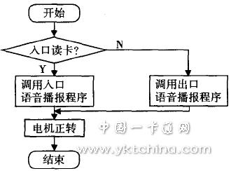
Figure 5 card reader interrupt service program flow chart
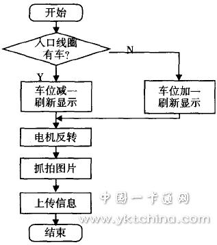
Figure 6 sense coil interrupt service program
5 Conclusion
This design uses SPCE061A to realize the automatic detection of the parking lot in and out of the vehicle, the automatic landing of the brake lever machine and the real-time display of the parking space information, and the intelligent management of the intelligent parking lot can be realized with the IC card information processing and image processing system. The application of the ground coil makes the detection of the vehicle accurate and ensures the reliability of the system.
Plug,Plug Power Stock,Plug Power Yahoo,Power Plug Stock
WENZHOU TENGCAI ELECTRIC CO.,LTD , https://www.tengcaielectric.com