1 Introduction
Daily daily water consumption varies greatly with seasons, staying up late, and commuting time, so there is often a sharp fluctuation in water pressure. Using PLC, variable frequency speed control device and pressure sensor to form a closed-loop control system to control the speed of the water pump, not only can ensure the constant pressure of the system pipe network, reduce the unreasonable water supply underpressure and overpressure, and the equipment and system run smoothly and reliably, saving energy. Significant.
2 Constant pressure water supply principle
After the water source or groundwater source from the municipal pipe network enters the reservoir, the water pump controlled by the frequency converter directly pressurizes the water into the water supply pipe network to each water point. According to the flow rate and pressure change of the water supply pipe network, the output frequency of the inverter is automatically controlled, and the rotation speed of the motor and the water pump is adjusted to achieve constant pressure water supply. The pressure change is transmitted to the arithmetic processing system through pressure detection (pressure sensor), and the system issues a pump acceleration or deceleration command to meet the pressure requirement, as shown in Figure 1. When a pump can not meet the pressure requirements at full speed, it will automatically input the No. 2 and No. 3 pumps; otherwise, stop the No. 2 and No. 3 pumps one by one. In short, let the pipe network achieve the purpose of constant pressure.
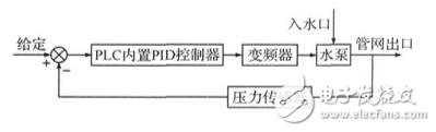
Figure 1 Schematic diagram of constant pressure water supply
3 system circuit design
The system is mainly composed of a Siemens S7-200 programmable controller, a Huifeng F1500-G inverter, pressure sensor, contactor, automatic switch, thermal relay, and 3 pumps. The main circuit of the system adopts one-to-multiple mode, as shown in Fig. 2. After the air switch is closed, when the AC contactor Q0.0, Q0.1, Q0.2 is closed, the water pump operates in frequency conversion; when the AC contactor Q0. 3. When Q0.4 and Q0.5 are closed, the pump runs at power frequency. Three thermal relays KH1, KH2, and KH3 protect the three motors from overheating when the motor is overloaded.
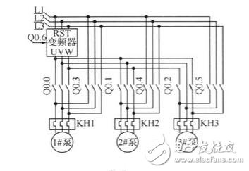
Figure 2 system main circuit diagram
4 PLC control program design
PLC and frequency converter are the core part of the system. The key to stable operation of the system depends on the rationality and feasibility of the PLC program and the setting of the inverter parameters.
4.1 PLC program flow
The system adopts two working modes: manual and automatic. The manual operation mode is mainly used for maintenance and faults. The three pumps can be controlled by the switch button according to the needs. The automatic operation mode is the daily operation mode of the system, and the automatic switch is closed. When the system starts, the single pump frequency conversion operation. According to the signal fed back by the pressure sensor, the frequency converter sends a variable frequency signal through the PID operation processing. When the running frequency of the variable frequency pump reaches the set upper limit frequency, the pump is converted to the power frequency operation and a water pump frequency conversion operation is added; when the frequency conversion pump operates at the frequency The set lower limit frequency is reached, and one power frequency pump operation is reduced.
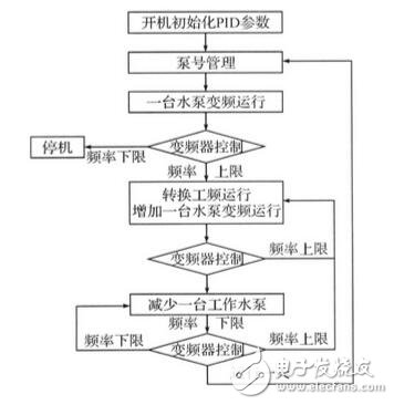
Figure 3 program flow chart
At the same time, through the pump number management subroutine, when the system automatically runs for one day, the pump number is automatically switched, and each pump works basically the same, which makes the system maintenance-free. The program flow is shown in Figure 3.
4.2 PLC programming
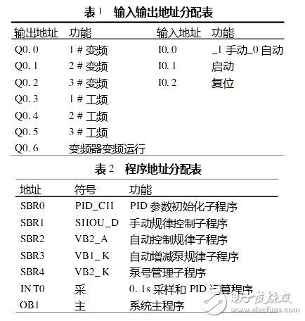
The PLC control program of this system consists of the main program and 6 subroutines. The program design adopts the ladder diagram design method, which is intuitive and easy to debug and maintain. Since the water supply system is a large but non-mutable system, the design is mainly based on the query method, and the interruption mode is supplemented by fuzzy PID parameter control. PLC input and output address is shown in Table 1, program address allocation is shown in Table 2, the main program is shown in Figure 4.
4.3 Inverter parameter setting
Inverter frequency conversion operation, when the pump speed is too low, the pump full lift is less than the actual lift, easy to form "idle" phenomenon, so the lower limit of the frequency conversion is set to 20Hz; when the pump runs at high speed (50Hz), the inverter V/F compensation function , often the actual speed of the pump is slightly higher than the power frequency running speed, taking into account the actual situation, the upper limit of the frequency conversion is set to 49Hz.
In addition, the inverter comes with undervoltage protection, overload protection and other functions. When the pump fails, it can issue a warning for maintenance.
4.4 PID fuzzy control
Fuzzy control technology overcomes the shortcomings of classical control theory relying on system digital model. It is an advanced control strategy based on linguistic rules and fuzzy reasoning. The system uses Siemens S7-200 to expand the analog processing hybrid module EM235 to complete the collection of the water pressure signal and the control of the inverter. The PLC receives the pressure value in the pipe network and compares it with the given value to calculate the deviation e and the deviation. The value of Δe is multiplied by the corresponding quantization factor, and is rounded and transformed into fuzzy variables E and ΔE. The control amount increment Δu is obtained and then multiplied by the scale factor to become the actual control amount domain value Δu(k), thereby calculating the total control amount u(k)=u(k-1)+Δu(k). This value is sent to the output register of the PLC. After processing, it becomes a voltage signal of 0∽5V and is sent to the inverter to change the motor speed to control the water pressure.
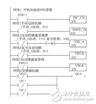
Figure 4 main program of constant pressure water supply system
4.5 Test situation
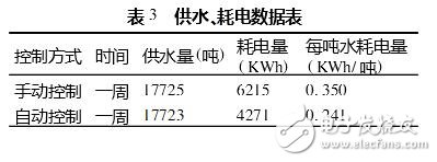
The system was tested on the ground for 2 weeks from July 11 to 24, 2008. In the first week, the system was manually operated, and the manual control pump was put into use. The second week was controlled by automatic operation and variable frequency speed control. Put into use. The measured data shows that the energy saving effect of the system is obvious, as shown in Table 3.
4 Conclusion
The constant pressure water supply system consisting of Siemens S7-200 series PLC, Huifeng F1500-G inverter and pressure sensor fully utilizes the built-in PID calculation module of PLC, automatically adjusts the inverter output frequency and puts the number of pumps into use. The purpose of pressure water supply; through the pump number management program, the pump number is automatically switched, so that the working condition of each pump is basically the same, the equipment utilization rate is improved and the maintenance cost is reduced; at the same time, the system fault diagnosis can be easily realized by the self-contained protection function of the frequency converter. The actual operation proves that the system has the characteristics of high reliability, high degree of automation, easy maintenance and high energy saving, and has great application value.
B&R Power Panel PP35 touch screen panel
Power Panel PP45 touch screen panel for B&R HMI repair
B&R Automation Power Panel PP65 touch panel screen
Power Panel PP100 HMI touch panel screen
Power Panel PP200 touch screen glass for BR automation repair
touch screen for Power Panel PP300 touch panel repair
B&R automation Panel PP400 touch screen panel
Power Panel PP400 embedded touch screen membrane
touch panel for Power Panel C70 touch screen repair
Membrane switch for B&R Power Panel PP65Keyboard membrane for Power Panel PP100 repair
Power Panel PP200 membrane keypad repair
membrane keyboard for Power Panel PP300 repair
B&R automation Panel PP400 membrane keyboard
Power Panel PP400 embedded membrane keypad repair
keypad for Power Panel C70 membrane switch repair
BR PP15 membrane keyboard switch keypad.
PHARMA FLEX touch screen panel glass repair
METTLER TOLEDO touch screen panel repair
GARVENS HMI touch screen panel glass
HMI Touch Panel Repair,Touch Membrane Repair,Membrane Keyboard Repair,Touch Screen Repair
GUANGZHOU VICPAS TOUCH TECHNOLOGY CO.,LTD , https://www.touchsuppliers.com