In view of the shortcomings of the traditional ward call system, this paper designs a PLC-based ward call system. When the patient requests the help of the medical staff through the button, the ward call system transmits the relevant request information to the upper computer system through the power carrier, and the medical staff gives the patient corresponding assistance according to the current request information.
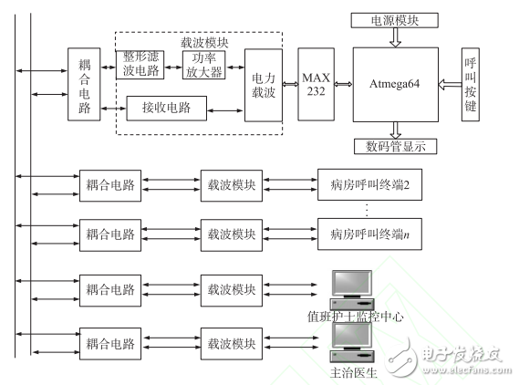
1, the overall system and working principleThis paper designs the hardware circuit of the ward call system according to the actual functional requirements of the ward call system. The system hardware circuit is mainly composed of a power module, a power carrier transmitting module, a power carrier receiving module, a clock module, a data display module, a call button module, a serial port module and a watchdog module, and the overall hardware circuit thereof is shown in FIG. 1 .

Figure 1 ward call system hardware block diagram
The system designed in this paper effectively solves the problems of complex structure, difficult construction and poor expansion of traditional ward call system. When the patient needs the help of the medical staff, the patient transmits the call request information to the corresponding attending doctor or nurse through the ward call system. After receiving the request information, the attending doctor or the on-duty nurse gives a corresponding response through the ward call system, thereby stabilizing the patient's mood. To improve the overall service level of medical care.
2. Hardware design of the control systemThe ward call hardware circuit is mainly composed of the following functional modules, which are a power carrier transmission module, a power carrier receiving module, a power module, a serial port module, a human-computer interaction module, and the like.
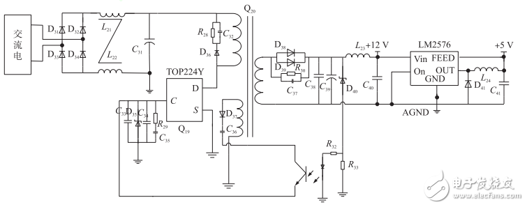
2.1, power moduleFor any system, the overall stability of the power module determines the overall reliability and stability of the system. Due to system size limitation and actual functional requirements, this paper designs a high performance switching power supply. The power supply uses the TOP224Y chip developed by American POWER Company as the power main control chip, and its circuit is shown in Figure 2.

Figure 2 switching power supply design circuit
The working principle of the switching regulator power supply is as follows: 220V AC power supply through the rectifier bridge and the filter capacitor output fluctuation DC power supply, the power supply is directly output to the drain pin of the TOP224Y chip, the TOP224Y chip is turned on, the power supply voltage is passed through the transformer Q20 primary coil and source The pole forms a loop, and the Q20 secondary coil outputs the power supply voltage. At the same time, the system uses the rectifier diode and the filter capacitor to rectify and filter the output power supply voltage. In order to ensure a stable power supply voltage of the switching power supply, the system uses the secondary winding of the transformer to sample the output power voltage. When the acquisition voltage is greater than 12V, the optocoupler illuminator is turned on, and the TOP224Y chip turns off the drain pin, thereby reducing the switch. The voltage level of the power supply output. Because the primary coil of the transformer has energy storage, it is easy to generate high spikes during the TOP224Y high-frequency switching process. In order to ensure that the system can work normally, the system designs an absorption loop pair composed of resistor R28, capacitor C32 and diode D36. The spikes are absorbed to effectively prevent damage to the TOP224Y chip caused by spikes in the switching power supply.
Mpo Patch Panel,Mpo-Lc Patch Panel,High Density 144F Mpo Patch Panel,Mpo Patch Panel For Data Center
ShenZhen JunJin Technology Co.,Ltd , https://www.jjtcl.com