First, three large quantities in the PLC
There is nothing more than three in the PLC: the amount of switching, the amount of analog, and the amount of pulse. Only by figuring out the relationship between the three, you will be able to master the PLC.
The purpose of the switch quantity control is to make the PLC generate the corresponding switch quantity output according to the current input combination of the switch quantity and the historical input sequence, so that the system can work in a certain order. Therefore, it is sometimes called sequential control. The sequence control is divided into manual, semi-automatic or automatic. The control principles adopted are three types: dispersion, concentration and hybrid control.
The PLC was developed after the introduction of microprocessor technology into the microprocessor. It can be conveniently and reliably used for switching control. Since the analog quantity can be converted into a digital quantity, the digital quantity is only a multi-bit switching quantity, so the PLC can also perform the processing control reliably with the converted analog quantity. Since continuous production processes often have analog quantities, analog control is sometimes referred to as process control.
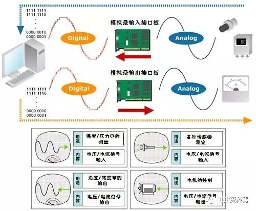
The analog quantity is mostly non-power, and the PLC can only process digital quantity and power. All the transitions between them are to have sensors that convert analog quantities into quantities. If this power is not standard, it must pass through the transmitter to change the non-standard power into a standard electrical signal, such as 4-20mA, 1-5V, 0-10V and so on.
At the same time, there must be an analog input unit (A/D) to convert these standard electrical signals into digital signals; an analog output unit (D/A) to convert the digital quantities processed by the PLC into analog quantities - standard Electrical signal.
Therefore, the conversion between standard electrical signals and digital quantities requires various operations. This requires a clear understanding of the resolution of the analog unit and the standard electrical signal. E.g:
The resolution of the PLC analog unit is 1/32767, the corresponding standard power is 0-10V, and the temperature value to be detected is 0-100 °C. Then 0—32767 corresponds to a temperature value of 0-100 °C. Then calculate the number corresponding to 1 ° C is 327.67. If you want to accurately measure the temperature to 0.1 °C, put 327.67/10.
Analog control includes: feedback control, feedforward control, proportional control, fuzzy control, etc. These are the calculation processes of the digital quantity inside the PLC.
The control purpose of PLC pulse quantity is mainly position control, motion control, and track control. For example: the application of pulse number in angle control. The stepping motor driver is subdivided by 10,000 per revolution and requires a stepper motor to rotate 90 degrees. Then the pulse value of the desired action = 10000 / (360 / 90) = 2500.

Second, the calculation of the analog quantity
The above is only a brief introduction. Different PLCs have different resolutions, and the range of physical quantities you measure is different. The calculation results may have some differences.
Note: Requirements for wiring for analog input
1. Use shielded twisted pair cable, but do not connect shield layer.
2. When an input is not in use, short the V IN and COM terminals.
3. The analog signal line is isolated from the power line (AC power line, high voltage line, etc.).
4. When there is interference on the power line, install a filter between the input part and the power unit.
5. After confirming the correct wiring, first power on the CPU unit, and then power on the load.
6. Turn off the power of the load before powering off, and then cut off the power of the CPU.

Third, the calculation of the pulse amount
The pulse amount control is mostly used for angle control of stepping motor, servo motor, distance control, position control, and the like. The following is a stepping motor as an example to illustrate the various control methods.
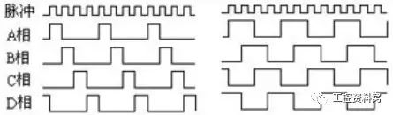
The formula is: the number of angular action pulses = the total number of pulses per circle * (set angle / 360 °).
The formula is: set distance pulse number = set distance / [(roller diameter * 3.14) / total number of pulses per circle]
The above is just a simple analysis of the control method of the stepper motor, which may differ from the actual ones, only for reference by colleagues.
The servo motor operates in the same way as the stepper motor, but considers the internal electronic gear ratio of the servo motor and the reduction ratio of the servo motor.
Photovoltaic Installation Tools
Pv Testers,Photovoltaic Installation Tools,Photovoltaic Tester,Solar Pv Tester
Sowell Electric CO., LTD. , https://www.sowellsolar.com