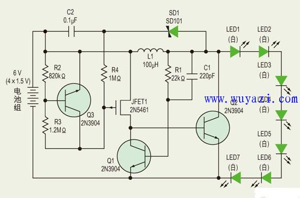
To drive more than one high-brightness white LED, designers need to choose whether to connect the LEDs in series or in parallel. Of course, every connection will bring a compromise to the design.
Parallel connections require only a low voltage across each LED, but ballast resistors or current sources are required to ensure uniform brightness for each LED. If the magnitude of the bias current flowing through each LED is different, their brightness is also different, resulting in uneven brightness of the entire light source. However, using ballast resistors or current sources to ensure consistent LED brightness will shorten battery life.
The use of a series connection essentially guarantees current consistency, but requires a higher voltage to be applied to the LED string. To achieve proper illumination, a conventional white LED requires a 3.6V bias voltage and a bias current of up to 20mA. Figure 1 shows a low-cost inductive boost circuit that can adjust the brightness of seven white LED strings.
This circuit can be divided into two parts: a boost circuit consisting of Q1 and Q2, and a control circuit consisting of Q3 and JFET1. Assuming Q1 is off, when the battery voltage is slightly higher than the VVB of Q2, the base of Q2 will flow a positive current (iB = (battery voltage VBE) / RJET1). At this time, Q2 is turned on, and the inductor L1 is grounded.
As the current on L1 increases at di/dt, the energy is preserved in the L1 magnetic field. As the current gradually increases, it also flows through the resistor RSAT of Q2 (SD1 and the LED string are in an off state). The collector voltage of Q2 is high enough to turn Q1 on. The base voltage of Q1 is connected to the collector of Q2 through a feedforward network consisting of R1 and C1. R1 is also used to limit the base current of Q1.
When Q1 is turned on, the base of drive Q2 is grounded, so Q2 is turned off, and the energy of L1 is released into the LED string as the magnetic field is weakened.
The fast zero return action of L1 imposes a forward bias voltage higher than 26V on the LED string, causing the LED to emit white light. Since the human eye does not feel the high frequency flicker of the LED, the circuit can provide illumination with constant brightness. When L1 discharge ends, Q1 returns to the off state.
During normal operation, this self-oscillating action is repeated until the battery voltage drops to a sum of VBE less than Q2 and the JFET1 voltage drop (approximately 1V), at which point Q2 is no longer conducting. The RSAT of L1 and Q2 and the switching characteristics of Q1 and Q2 also affect the oscillation period and duty cycle.
The voltage of the battery pack (4 alkaline batteries) is increased above 26V to provide forward bias to the LED string consisting of 7 white LEDs in series.

Q3 is biased by a small DC current (less than 20uA) flowing through R4 to regulate the channel resistance of JFET1 to regulate battery leakage current to extend battery life. The gate voltage of JFET1 is about 0.9V higher than the battery pack voltage. Here the p-JFET is used as a depletion mode device, and when VGS is equal to zero, the p-JFET is turned on.
Vacuum UV Curing Machine,Vacuum Curing Machine,UV Machine
Shenzhen Jianjiantong Technology Co., Ltd. , https://www.jjtscreenprotector.com