introduction
This article refers to the address: http://
This application note describes a reference design (RD) for an AM/FM automotive antenna. The design uses a highly integrated AM/FM low noise amplifier (LNA) MAX2180 for active antenna modules. The LNA integrates Maxim's automatic gain control technology on both the AM and FM signal paths with user selectable set points. The maximum gain of the AM and FM signal paths can also be varied to meet a wide variety of user needs. RD provides a detailed demonstration of the flexibility and performance of this integrated automotive solution.
Overview
Automotive antennas require smaller, more integrated solutions while maintaining the high performance required by modern AM/FM wireless communication devices. Some solutions require automatic gain control (AGC), while others use fixed gain LNAs for the lowest cost. Some solutions provide a regulated supply voltage for the active antenna, but most are still battery powered. The challenge for antenna solution providers is how to meet a wide range of industry requirements while avoiding discrete solutions that require repeated design or without the use of expensive ICs (which still require external PIN diodes and regulators). With limited resources and space, the ideal solution for antenna vendors is necessarily high-performance, low-cost, and very flexible ICs that can easily meet a variety of requirements without redesign, BOM changes, and board changes.
A few vendors now offer integrated AM/FM solutions for active antennas. Unfortunately, they need an external PIN diode to provide AGC. These solutions also require a regulated power supply or an external adjustment tube when running on battery power. External components add cost and expand the footprint of the solution. If AGC is not required, the solution typically uses discrete components to achieve the lowest cost. The problem with discrete designs is that any change in gain, supply voltage, or footprint will result in a redesign that will take up more design resources, and design resources are scarce in most cases.
Optimal antenna solution and MAX2180
Maxim Integrated Products has developed an AM/FM antenna solution that integrates all active components to meet today's demanding automotive antenna needs. The antenna uses the MAX2180 LNA. The MAX2180 incorporates an internal high-voltage CMOS process that integrates AM and FM AGCs, as well as high-voltage regulators, in a small 4mm x 4mm TQFP package. This design avoids all PIN diodes and external voltage regulators or pass transistors, as well as battery or regulated power supplies. The MAX2180 achieves maximum AM and FM gain with variable AGC setpoints. It also includes an antenna monitoring function that draws 15mA into the current under fault conditions.
The LNA's on-chip voltage regulator operates from 7V to 24V. To prevent overheating damage, the integrated temperature sensor limits the maximum junction temperature by the foldback current. This ensures that the amplifier remains operational under all environmental conditions.
The AM input is high impedance, the output is low impedance, and the FM amplifier provides 50Ω input and output impedance. The maximum AM gain can be set from 0dB to 6dB by changing the external resistance. The maximum FM gain can vary from 5.8dB to 8.5dB (R1 = 0Ω). To improve the noise figure, R1 should be 390Ω, increasing the gain range to 10.0dB to 10.8dB. Both signal paths use Maxim's patented AGC circuit with a gain control range of 30dB. In addition, the AGC setpoint is variable to provide the host with the desired maximum output level.
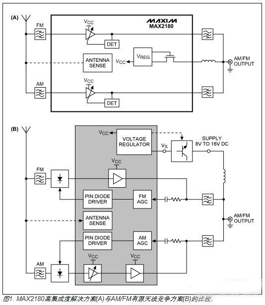
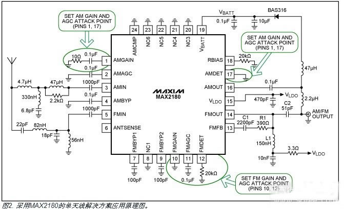
When designing with the MAX2180, the design can be simplified by using the tables in the data sheet to select the desired signal path gain and AGC set point. This range of custom parameter values ​​allows a single design to meet multiple needs without the need to rearrange the board. As shown in Figure 1, the MAX2180 offers greater integration than competing solutions, while offering the flexibility to meet a variety of needs. Figure 2 shows the application schematic of a single antenna solution.
Design example
Our test case is a low gain antenna for small cars. This application requires more gain, but the short cable in a small car reduces the loss from the antenna to the host. The target maximum input level is +80dBμV for AM and +95dBμV for FM.
AM: Pin 1 resistance = 0Ω, gain is 6.5dB (Table 1); Pin 17 is shorted to ground and the AM output AGC set point is +79dBμV (Table 2).
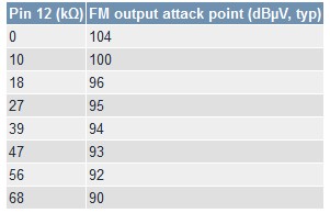
FM: Pin 10 is shorted to ground with an FM gain of 8.5dB (Table 3); pin 12 to ground = 39kΩ and FM output AGC protection point is +94dBμV (Table 4).
Table 1. AM signal path gain
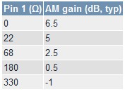
Table 2. AM Signal Path Set Point
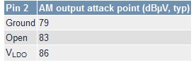
Table 3. FM Signal Path Gain
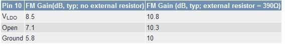
Table 4. FM Signal Path Setpoints
The mining industry is taken as a risky business, with health risks that are varied and often quite serious, and it is important for miners to protect themselves accordingly, thus the personal enviroment detection equipment is essential for miners during the operation.
The Gas Measuring Instrument, Heat Stress Detector, Dust Monitor,Air Purifier from Win3 safety helps the miners to detect the potential risk and enhance the safety, we are dedicated to mprove safety and enhance efficiency of global mining and industrial enterprises
Environment Detection Equipment
Gas Detector,Gas Detector,Gas Detection,Gas Measuring Instrument
ZHEJIANG HUACAI OPTIC-TECHNOLOGY CO LTD , https://www.win3safety.com