With the development of the economy, the city's public transport industry has developed rapidly. The main manifestations are: vehicles have changed, stations have increased, operating hours have been extended, and routes have increased. People have felt this gratifying change when they travel. However, with the acceleration of the pace of life and the improvement of the quality of life, passengers have long been unable to satisfy the existing service quality.
This article refers to the address: http://
Passenger service requirements are not only reflected in the ride, but also in the front and back of the ride; not only need to have a ride, but also need to take a good car, good ride. These multi-level and diversified requirements cannot be achieved by traditional operation modes and scheduling methods. Only the implementation of intelligent public transportation systems can fundamentally solve these problems.
The implementation of the intelligent public transport system not only can bring huge benefits to the passengers, but also enhance the image of the city. It also believes that the bus companies can save a lot of operating costs and improve the scientific management level. Therefore, the construction of the intelligent public transport system has significant social and economic benefits.
The intelligent public transport system consists of the following components:
1) Vehicle equipment subsystem, referred to as "vehicle terminal";
2) Station intelligent electronic station subsystem;
3) Bus management system.
In this paper, the vehicle-mounted equipment subsystem-vehicle terminal is mainly discussed.
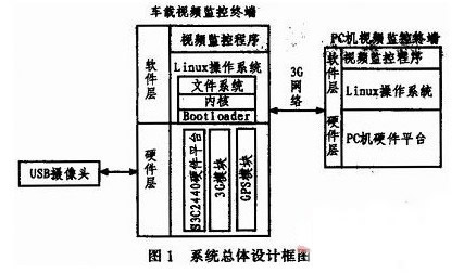
1 system overall design
In this paper, a smart bus terminal based on GPS and 3G is studied. In short, it is to study the vehicle terminal equipment of the car body. The research in this paper is mainly divided into three parts: video surveillance part; GPS positioning part; transmission part through existing 3G network.
In the video surveillance part, two cameras are mainly installed outside the cabin, and four cameras are arranged inside the cabin. A camera is arranged on the outside of the car to monitor the front and rear conditions of the car body, providing strong evidence for the responsibility of the traffic accident.
Inside the compartment, a camera is set up at the driver's office to monitor whether the driver has a phone call, chat or other illegal operation; a camera is installed at the ticket box to monitor the phenomenon of ticket smuggling; a camera is placed in the middle of the car body. It is used to prevent passengers from hitting porcelain claims, stealing inside the car, etc., and reducing the crime rate on the bus. The lower door is equipped with a camera to watch the passengers get off the bus, whether the passengers all get off the bus, whether there are passengers getting off the back door and so on.
The GPS positioning part realizes perfect navigation function. The location information of the bus is determined by the GPS global positioning system, and the location and road condition information of the bus can be transmitted to the PC monitoring terminal in real time, which plays a key role in the scheduling of the vehicle.
In the 3G network transmission part, in recent years, China's 3G network has matured and can transmit video information efficiently. This system transmits the video information and CPS information collected on the bus to the control terminal through the 3C network to realize the bus operation. Full monitoring of the time. The overall design of the system is shown in Figure 1.
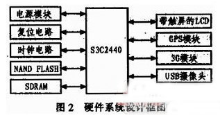
2 system hardware design
Hardware design, the system uses ARM microprocessor S3C2440 chip as the main control chip, the system expands 128MB NANDFLASH and 64MB SDBAM for storage, which can better store video information. The system's peripheral expansion modules include a universal USB camera, GPS module, 3G module and LCD display. The hardware block diagram of the system is shown in Figure 2.
2.1 The choice of the main control chip
The monitoring terminal designed by the system requires multi-path transmission, strong real-time performance and low power consumption. Therefore, the main control chip of this system selects the ARM9 processor whose core is ARM920T. Because S3C2440 chip is widely used, the chip is rich in resources, the data is complete, and the price is moderate, so it is chosen as the microprocessor of the system.
The processor is a RISC-based 32-bit microprocessor that operates at 400 MHz and can be up to 533 MHz, meeting the processing speed requirements of the system. The processor also integrates a rich communication interface and control. The device effectively reduces the complexity of the system and provides a good hardware platform for system development.
2.2 Camera module selection and connection
The text is monitored in the form of dynamic video. The mesh V2000 camera is selected. The image sensor and digital signal processing chip are Omnivision's OV7620 and OV511. It has fast imaging speed, high picture quality, low cost and good versatility.
It adopts USB interface, does not require video card, can be plug and play, and uses the image to make the image clear and coherent, and the mosaic ratio is low. Provides a reliable hardware foundation for good recording of video. The mesh V2000 camera is directly connected to the USBHost interface integrated on the CPU through its USB interface.
The OV7620 is a highly integrated, high resolution color image sensor. It has a resolution of 640x480 and a transfer rate of up to 30 frames per second. The OV7620 is controlled by the SCCB (Serial Camera Control Bus) protocol, and its SCCB (Serial Camera Control Bus) interface can be used to set and read image data.
The OV511 is the camera's main control chip. Its on-chip high-performance compression engine can achieve an image compression ratio of 7:1, ensuring fast image transmission from the image sensor to the main controller.
2.3 GPS module selection and connection
The GPS module of this system uses the GB-87 module of HOLUX. The module supports the NMEA0183 protocol, supports V3.3-V5.5 voltage input, TTL interface level, and baud rate can be set.
In this system, the GR-87 module is connected to the main board through a 6PIN cable. The 1 pin is the power input pin and is connected to the 5 V power supply. The 2 and 3 pins are the data receiving and transmitting of the GPS module, and the 5 pin is grounded.
During operation, the serial port 2 of the GPS module communicates with the main controller S3C2440, and the GPS positioning data is output periodically by the setting module, and the GPS data is processed by the main controller to extract useful information such as latitude and longitude, time, etc., for automatic reporting and punctual assessment. Provide reliable data to ensure the realization of the reporting and punctual assessment functions.
2.4 3G module selection and connection
According to different wireless interface technologies, the existing 3G technology can be divided into Unicom's WCDMA technology, Telecom's CDMA2000 technology and mobile TD-SCDMA technology.
Considering the transmission bandwidth, network stability, practicability and other factors, the system uses telecom CDMA2000 as the wireless network transmission, and uses the MC8630 module of ZTE Corporation as the video data transmission module.
The MC8630 module has functions such as voice, short message, data service and GPS. The working frequency band is 800MHz. The dual-antenna receive diversity technology and equalization technology can achieve an uplink rate of up to 3.1 Mbit/s and a downlink rate of up to 3.1 Mbit/s. The MC8630 module can be connected to the MIN2440 (S3C2440 main board development board) processor through the USB interface to realize the packaged video data transmission.
3 system software design
At present, the common embedded operating systems mainly include WinCE, Linux, Vxworks and so on. The source code of the Linux operating system is completely open. Because of its high efficiency and stability, rich network resources, small kernel, fast execution, and good portability, it is widely used in the field of embedded systems. Therefore, the embedded Linux operating system was chosen as the software development platform of the system.
In software design, you first need to establish a cross-compilation environment between the microcontroller and the PC to compile the bootloader and the Linux kernel. Then complete the migration of the bootloader Bootloa der; configure and compile the Linux kernel; make the root filesystem and the underlying driver.
Finally, through the preparation of the upper application to complete image acquisition, GPS information collection, 3G transmission and other functions. The following sections detail the design ideas of several major programs.
3.1 Image Acquisition Program
In terms of video capture, the camera used in this article is the mesh V2000, which is a camera with ov511 as the main control chip. The reason for choosing it is because the Linux kernel comes with the ov511 driver, so you don't have to write your own camera driver. Just select it when you customize the kernel. Save time for development.
When the Linux system starts normally, plug in the V2000 camera. If the driver is successfully loaded, the device file device0 will be created for the camera in the /dev/v41/ directory. The upper application can access the camera through this device file to realize the function of capturing images. . The embedded system platform has been successfully built. To obtain images in real time, you need to use the V4L (Vidio For Linux) programming interface to implement the image acquisition program.
Considering that the 640x480 RGB image data collected by the camera is large, the image compression function put_image_jpeg is used to convert the image into JPEG format, which reduces the occupied NandFlash space when storing, and also reduces the backhaul of the monitoring center through the 3G network. The transmission cost and the transmission are guaranteed to be successful.
3.2 GPS resolution program
The GPS receiver HOLUX GR-87 module output data format conforms to the NMEA.183 standard. The NMEA.0183 protocol is a serial communication data protocol developed by the National Ocean Electronics Association. All input and output information is a line of ASCII characters. One of its messages is called a Sentence. Each statement starts with a "$" and ends with a carriage return (), with a number of fields separated by commas.
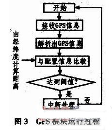
Since the GPS module setting information is lost due to power failure, the GPS module is initialized every time the system is started. Set the module to output GPS information once per second. After the system is started, the module receives the GPS information, and then parses out the GPS information, and calculates the actual distance according to the parsed latitude and longitude information and the site information stored in the data area. If the distance reaches the threshold, the GPS station is interrupted.
The GPS module receiving module follows the NMEA.0183 protocol and can output data frames in multiple formats, starting with "MYM". The output data is in ASCII characters and contains information such as latitude, longitude, speed, date, heading and satellite status. The system uses only the $GPRMC positioning data frame format.
After the system is started, the GPS module is set through the serial port. Since the system does not require high real-time performance, the GPS is set to output RMC data once every second. The idea of ​​extracting the GPRMC statement is to set a data buffer, put the received GPS data into this buffer, and when the buffer is full, find in the buffer whether to accept the GPRMC positioning statement, if not received Then reconnect the GPS data.
If you find the GPRMC positioning statement, you must also determine whether the maximum number of bytes in the buffer from the buffer is greater than 62 bytes (because the number of bytes in the GPRMC positioning statement required in this program is 62). Then, through the multi-program, the relevant latitude, longitude, time and speed information is extracted and processed through the data processing thread. The running process is shown in Figure 3.
3.3 3G module parsing program
The MC8630 module driver can be generated by cross-compilation of the driver source. The MC8630 module driver for the loading and dial-up connection of the MC8630 module can be generated by cross-compilation of the driver source code. The process of loading and dialing connections for the MC8630 module is as follows:
1) Before compiling, first make sure that the compile driver and the compile kernel have the same build environment, that is, the cross-compiler tool with the same version number (the system Linux version number is 2.6);
2) Modify the driver source Makefde file, including adding the kernel source directory and compilation tools;
3) After the Make is compiled, generate ztemt.ko;
4) insmod ztemt.ko, generate 4 device nodes /dev/ttyUSB0-ttyUSB3;
5) mknod/dev/ttyUSB0 c 188 0, create a device node;
6) Write a dialing script, a chat configuration file, and an account password configuration file for Linux;
7) Add kernel options to compile the kernel that supports PPP protocol;
8) pppd call evdo dial-up connection, ifconfig queries whether the network is connected;
9) ppp-off interrupt connection.
4 Conclusion
The intelligent bus terminal designed by the system adopts advanced 3G/GPS technology, realizes the real-time monitoring and dispatching of the bus operation vehicles through the collection, transmission and processing of the information of the bus vehicles during operation, and quickly adjusts the operation status of the bus vehicles. Improve the efficiency of vehicle work, make the best use and distribution of bus resources, and achieve the intelligence of public transport.
Lithium Battery Chargers,48V Lithium Battery Charger,48V Bike Lithium Battery Charger,48V Bicycle Lithium Battery Charger
Changxing Deli Technology Co., Ltd. , https://www.delipowers.com