High-brightness LEDs (HBLEDs) are rapidly gaining popularity in the automotive, consumer electronics and industrial markets. Bright colors, long life and high energy efficiency are some of the reasons why high-brightness LEDs are the future of lighting applications.
This article refers to the address: http://
In the automotive industry, HBLED technology differentiates vehicles from styling, safety and fuel economy, from simple switching lighting, LCD backlighting to extremely high brightness headlight applications. However, efficient and reliable control of the brightness of HBLEDs is not an easy task; power stage efficiency, thermal design and EMC are the most critical design challenges in applications involving HBLEDs. Typically, a dedicated constant current driver (CCD) is used to drive the HBLED string to solve most important design problems and simplify the design. However, CCDs are usually more expensive than microcontroller-based solutions. This article describes the use of 8-bit microcontrollers (MCUs) and low-cost separation solutions to implement intelligent HBLED lighting control, thereby avoiding the use of expensive analog drives or CCDs.
Important features of high-brightness LEDs
As is the case with low-intensity LEDs, the luminous intensity of a high-brightness LED is proportional to the electrical flow that passes through it. This current is often referred to as forward current (IF) and is in the range of 100 mA to 1000 mA in the HBLED. At the same time, whenever the HBLED is polarized, a voltage drop occurs, called the forward voltage (VF). In HBLEDs, luminosity and chromaticity are directly proportional to IF, so precise control of the current through the HBLED is critical.
HBLEDs with the same part number and technical specifications do not necessarily have exactly the same VF value. When the current IF through the two HBLEDs is the same, their backward voltage VF may be different. Therefore, controlling the intensity of the LED by means of a constant voltage may result in a difference in density between the HBLED and the HBLED, and to ensure that all HBLEDs have the same brightness, a current control must be provided.
Not only is the luminous intensity related to the current through the HBLED, but the chromaticity is also related to the HBLED current. In order to maintain the HBLED color, the HBLED must be driven with a constant current. This solution will use PWM (Pulse Width Modulation) to provide a lower average current in HBLED (light intensity) while maintaining the same instantaneous current (LED color).
As the HBLED current increases, power consumption will also increase. The current is 350mA. HBLEDs with a voltage drop of 3V consume approximately 1 watt of power. This dissipation can cause HBLED overheating and long-term performance degradation if proper thermal management is not performed. Another important aspect of thermal design is that the intensity of HBLED illumination is inversely proportional to the junction temperature of the LED. As the temperature increases, the color of the emitter enters a higher wavelength.
The challenge of driving high-brightness LEDs
In low-intensity LEDs, it is very common to use resistors to limit IF current. In HBLEDs, the rated power of the resistor must be higher, which can lead to inefficient systems. Therefore, in HBLED systems, Switch Mode Power Supplies (SMPS) are used to increase efficiency and reduce power consumption. Since SMPS requires energy storage components (inductors and capacitors), the price is usually more expensive; at the same time, SMPS can also cause noise or EMI problems.
A group of HBLEDs can be driven simultaneously in parallel or in series. Parallel driving allows each HBLED to have a different illumination intensity. However, if a control loop is required, each HBLED will require a dedicated control, so the cost is too high for a large number of HBLEDs.
When connecting HBLEDs in parallel, each string requires only one drive and control loop, and the current through all of the HBLEDs in the series is the same, providing them with a relatively constant brightness. Depending on the number of LEDs in series, the voltage required for line penetration may be lower or higher than the input voltage.
Adopt a microcontroller-based solution
There are a number of solutions on the market that drive HBLED constant current, some based on dedicated intelligent analog drivers and the other using digital signal processors (DSPs) or microcontrollers with independent analog drivers.
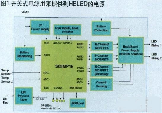
It is widely believed that MCU-based solutions are not the best way to perform HBLED constant current control, especially when the system uses a switched-mode power supply with discrete components to become unstable and impossible to pass EMC certification. Freescale Semiconductor has created a design example for dual string HBLED lighting control. The HBLED is based on the S08MP16 eight-bit microcontroller. The MCU is responsible for measuring the current feed from the LED string and processing it using the PID control algorithm to control the operation of the independent buck-boost switching power supply, ensuring the best through the HBLED string. Current flow.
The microcontroller is also responsible for monitoring user input, battery voltage and temperature sensors, diagnosing real-time LED power supply status, and special communication functions such as LIN functions can be implemented in the same microcontroller.
The switched-mode power supply is used to provide power to the HBLED. It is a discrete buck boost topology that operates from 1 to 18 LED strings (0V to 65V continuous range) and 500mA at 350kHz Output current. The application block diagram is shown in Figure 1.
Switch mode power supply design challenges
For a large number of HBLEDs, a buck boost supply is required to sense an output voltage (VOUT) above or below the battery voltage (VBAT).
There are many buck boost topologies available today, such as CUK circuits or SEPIC converters, each with different requirements and respective advantages in terms of required component count, positive and negative voltage reference, and efficiency.
The switch mode power supply chosen in this design combines a buck converter with a boost converter that uses a common inductor and capacitor to change the operating mode from buck to boost or buck to buck. The need depends on the state of transistors Q1 and Q2, as shown in Figure 2.
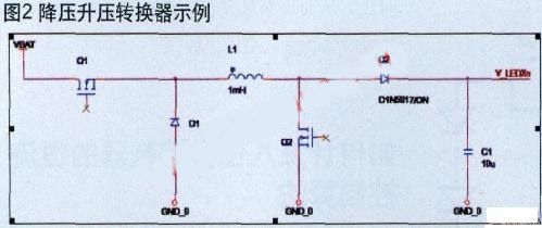
This topology reduces cost and does not require additional inductors and capacitors. In addition, depending on the mode in which the switch mode power supply operates, its transfer function is reduced to a common buck or boost converter, simplifying the design from a control perspective.
In order to control the EMC using a separate switch mode power supply topology, buffer filters need to be set and added to switching transistors Q1 and Q2; and the software control strategy needs to be set to center-aligned PWM and on/off delay between the two channels. .
Select the appropriate microcontroller for constant current HBLED control
Switch mode power supplies (SMPS) require accurate switching frequency and duty cycle, and PWM signal jitter is reflected in the output voltage, which is reflected in the HBLED intensity. At the same time, in order to save the inductor cost and capacitor size, the switching frequency must be increased to tens of thousands of Hertz. Analog-to-digital converter resolution and channel availability are also important for monitoring and controlling HBLED current and voltage at any time.
In order to achieve HBLED constant current control, the S08MP16 measures the HBLED string current reflected in the current sense resistor, which is connected in series with the HBLED string. The S08MP16 is an embedded 12-bit analog-to-digital converter that uses a small resistor value and consumes very little power. In addition, by using an ADC and a resistor divider, the SMPS output voltage under overcurrent and overvoltage conditions can be measured and the open load can be diagnosed.
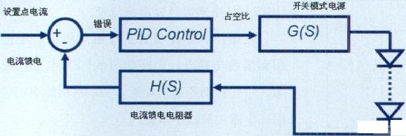
Figure 3 Embedded PID Control Block Diagram
To control the switching power supply frequency and duty cycle, the FlexTimer (FTM) module can be used; high-frequency and high-resolution pulse width modulation (PWM) can be generated using a timer operating frequency of up to 40 MHz in a suitable automotive version. The string can be operated with more HBLEDs, and the HBLED intensity will not be unstable when performing small operations. In addition, the Programmable Delay Module (PDB) is used in this application to synchronize the ADC readings with the PWM switching frequency to ensure that the ADC readings are only displayed when the current is stable in the ON state.
How to calculate the constant current control algorithm of an eight-bit microcontroller
In most cases, a simple control loop ensures proper driving of the HBLED; with closed-loop control, the module compensates for battery voltage, temperature, or any other parameter change in the open loop that may affect the HBLED current.
For constant current control, the module provides the voltage required to hold the HBLED string at a specified voltage, which also allows the number of HBLEDs on each string to be flexibly set without further calibration and hardware changes.
To integrate control loops in 8-bit microcontrollers, avoid using floating-point libraries; in this case, you can use 16-bit variables to complete the calculation.
in conclusion
It is easy to drive HBLEDs, but it is not that simple to drive HBLEDs efficiently and reliably without increasing costs. With an 8-bit low-cost microprocessor, as long as it has the right peripherals, it can save costs and drive HBLEDs efficiently and reliably. Hardware and firmware design is critical to ensure that HBLED applications exhibit the expected performance during the expected life cycle of the module.
Although the design of this paper is for automotive applications, these concepts and solutions can be used in many other industrial and consumer electronics applications that use HBLEDs.
Blow Suction Vacuum Cleaner: This mini usb vacuum cleaner is with both blow and suction function, it not only can be used for suction dust, also can be used for blowing dust. This blow suction portable vacuum cleaner can also clean some water.
Handheld Mini Vacuum Cleaner : This small vacuum cleaner can be used for cleaning hidden dirty of notebook keyboard, printer, pet food, office, kitchen table, or other small household appliances.
Portable wireless mini Car Vacuum Cleaner : This usb car vacuum cleaner can be used for cleaning car vent, dashboard, storage cabinet, sand, dust, paper, food debris, and so on.
Wireless Handheld Vacuum Cleaner: this Small Vacuum Cleaner power supplied by usb port, which is very easy and convenient to use and store.
Easy to use: this mini Cyclone Vacuum cleaners` filter can be washed by water. Just open the dust pot and take it out, then wash it clean and reuse after it dry.
This Multifunctional Rechargeable Vacuum Cleaner is a good home helper for you. As a small Portable Vacuum Cleaner, it is very easy and convenient to use and to store everywhere you like.Blow Suction Vacuum Cleaner
Small Vacuum Cleaner,Shark Pet Vacuum,Black And Decker Vacuum,Cheap Vacuum Cleaners
SHENZHEN HONK ELECTRONIC CO., LTD , https://www.honktech.com