With the rapid development of the automobile market and the improvement of people's living standards, more and more automobiles have entered ordinary families. Car theft prevention is particularly important, and it has become an important social problem to be solved urgently. At present, most of the car anti-theft alarms on the market are retrofitted car anti-theft devices and car anti-theft devices that use electronic password keys. Installed car anti-theft devices mainly use series-connected lines. For thieves who are proficient in car circuits, the anti-theft circuit can be easily avoided by using the jumper method. The anti-theft system is like a dummy. For car anti-theft devices that use electronic password keys, thieves generally steal the keys and use the remote control to quickly find the car and carry out the theft. This shows that the existing anti-theft devices of automobile anti-theft devices are not reliable. The fingerprint identification module is used to verify the identity of the owner and assist a variety of alarm measures to complete the design of the car anti-theft alarm, which can ensure the safety of the car as much as possible without changing the overall circuit of the car.
Fingerprint recognition is a kind of biometric identification. It uses the uniqueness of fingerprint features and life-long invariance to authenticate personal identities. It has extremely high security and ease of use. In this paper, fingerprint identification technology is applied to the automobile anti-theft system, and combined with the GSM wireless communication network to achieve remote alarm, effectively guarantee the safety of the car.
1 System structure and working principle
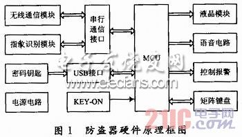
The car alarm is mainly composed of MCU, fingerprint recognition module, wireless communication module, LCD display screen, voice circuit, electronic password key interface circuit, keyboard, control circuit and power circuit. Its hardware block diagram is shown in Figure 1. MCU selects the enhanced 32-bit chip STM32F10 3VC based on the low-power embedded ARM CortexTM-M3 core introduced by STMicroelectronics. Its working voltage is 2.0-3.6 V, and this design uses 3.3 V The maximum operating frequency can reach 72 MHz, with up to 80 fast I / O ports, all I / O ports can be mapped to 16 external interrupts, and almost all ports can tolerate 5 V signals. There are 256 KB of FLASH, 2 I2C interfaces, 2 SPI interfaces, 3 USART interfaces, 3 16-bit timers, each timer has up to 4 for input capture / output comparison / PWM or pulse Counting channels and incremental encoder input, 2 watchdog timers (independent and window type), etc. "KEY-ON" in Figure 1 is the position of the car key, taken from the key switch, and sent to the PE10 of STM32F103VC after photoelectric coupling. Wireless communication module and fingerprint recognition module are connected to USART1 and USART2 of STlM32F103VC via RS 232 transceiver MAX3232 respectively; the password key is realized by U disk, USB interface is connected to SPI1 of STM32F103VC; voice circuit is connected to SPI2 of STM32F103VC; 4 & TImes; 4 keyboard and PE0 ~ PE7 Connected, LCD display data is provided by PD0 ~ PD7.
The main working principle is as follows: After the owner stops the engine, the anti-theft device enters the locked state. At this time, if the car key is not in the ON position, fingerprint recognition cannot be performed; only when the car key is in the ON position, the fingerprint recognition can be used to unlock the anti-theft device and automatically ignite. In the locked state, the car's oil circuit, circuit, etc. are cut off, and the car key cannot be ignited; if the connection between the fingerprint collection module and the control box is forcibly cut, or the car key is forcibly ignited without recognizing the fingerprint, the car will pass Flashing lights and wireless communication network alarm. Insert the password key in the locked state to enter the unlocked state, and perform fingerprint registration / deletion, mobile phone number setting and emergency ignition through the keypad according to the LCD and voice prompts.
2 Hardware design and implementation
2. 1 USB interface circuit
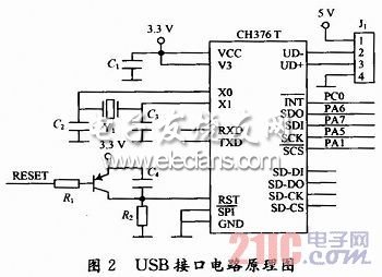
The USB interface circuit is mainly realized by the file management control chip CH376T. The CH376T supports the USB device mode and the USB host mode, and has built-in basic firmware of the USB communication protocol, firmware of a dedicated communication protocol for handling MassStorage mass storage devices, and communication interface firmware of the SD card. , FAT16 and FAT32 and FAT12 file system management firmware, support commonly used USB storage devices and SD cards. CH376T supports two kinds of communication interfaces: SPI interface and asynchronous serial port. This design uses the SPI interface to communicate with the MCU. The circuit connection is shown in Figure 2. Serial data input SDI, output SDO and clock SCK are respectively connected to SPI1_MOSI, SPI1_MISO and SPI1_SCK of STM32F103VC, the interrupt request output terminal INT is connected to PC0, and the chip select terminal SCS is controlled by PA1. RESET in Figure 2 is the system reset signal, the crystal oscillator Y1 selects 12 MHz. When the car mainly performs fingerprint registration / deletion or emergency ignition, connect the password key (U disk) to J1 to read the password information.
Â
2.2 LCD display
The liquid crystal display uses the SMG12864G3-ZK standard Chinese character and graphic dot matrix liquid crystal display module. The dot matrix liquid crystal display can display 128 & TImes; 64 dot matrix or 4 lines & TImes; 8 Chinese characters, built-in ST7920 interface type liquid crystal display controller, with internal GB2312 code simplified Chinese character library (16 & TImes; 16 dot matrix), can be directly connected with MCU, with 8-bit parallel and serial connection. This design uses parallel connection with STM32F103VC. The data terminals DB0 to DB7 are connected to PD0 to PD7 of STM32F103VC. The data / command selection terminal RS, read / write control signal R / W and enable terminal E are connected to PB2, PA14 and PA15, respectively. . The liquid crystal display in this immobilizer is used to display the operation method and operation content.
30-50W Solar Street Lights,30W Solar Street Light,45W Solar Street Light,50W Solar Street Light
Yangzhou Bright Solar Solutions Co., Ltd. , https://www.solarlights.pl