Abstract: Aiming at the special needs of the vehicle command and control task computer, this article proposes a system design scheme that uses the PowerPC processor as the control core, the CPCI bus as the system backplane bus, and the FlexRay as the communication bus. Tests have proved that this solution has the advantages of easy expansion, high integration, and strong real-time performance, and can meet the requirements of the vehicle application environment of the command and control task computer.
Keywords: FlexRaV; bus; vehicle-mounted application environment
introduction
In modern warfare, drones have many advantages over man-machines, such as low cost, zero casualties, high maneuverability, and reusability. Their range of use has been extended to military, civilian, and other fields. It can be used for reconnaissance, surveillance, communication relay, electronic countermeasures, battle results evaluation, etc. in military use; it can be used for sampling and geodetic surveying, meteorological observation, urban environment monitoring, earth resource exploration, forest fire prevention, nuclear pollution and biochemical pollution areas Monitoring etc. UAV systems are usually composed of airborne systems, data links and ground stations.
The ground station is the hub of the UAV system, and its main functions include: mission planning, flight control, information processing and display, target detection and positioning, and data recording. Vehicle-mounted ground stations are favored by users because of their good maneuverability, ease of rapid deployment, and the ability to quickly reach the vicinity of the mission area. However, vehicle-mounted ground stations face harsh environments such as high and low temperature, high humidity, shock, vibration, electromagnetic radiation interference, and the harsh requirements on their performance, volume, weight, and power consumption. Ordinary commercial computers cannot meet the requirements and control of vehicle-mounted environments. Real-time requirements. This paper proposes a command and control computer design and implementation method for the needs of a vehicle-mounted UAV ground station.
1 System function analysis
The UAV ground station command and control computer is used for UAV tracking and command control. It receives the image signal transmitted by the remote sensing of the UAV through the radio receiver and sends it to the driver of the vehicle-mounted ground station after image processing. At the same time, the command control computer performs image storage. The driver of the vehicle-mounted ground station can monitor the flight of the drone and the execution of its tasks. The command transmitter of the ground station can send control commands to the drone. After receiving the drone, it can continuously adjust the flight route according to the commands. mission accomplished. Figure 1 is the system cross-link diagram of the command and control computer of the vehicle-mounted UAV ground station.
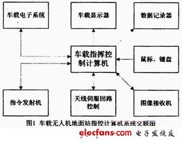
The vehicle-mounted command and control computer is the core of the vehicle-mounted ground station and an important control component for the normal and orderly operation of the system. The command and control computer is responsible for organizing and managing the internal equipment of the vehicle ground station, so that the equipment in the ground station can coordinate and work in an orderly manner, and exchange data with the vehicle electronic system through the FlexRay bus to ensure that the ground station captures the mission area image signal sent back by the drone. The control commands of the ground station driver are transmitted to the drone in time. Its main functions are as follows:
(1) Information exchange between ground station and vehicle-mounted electronic system;
(2) Collect the control commands issued by the driver, and transmit the commands to the command transmitter, which is modulated by the command transmitter and then transmitted to the drone, and at the same time send the control commands to the recorder for recording;
(3) Control the rotation of the antenna servo system of the command transmitter and image receiver to align the main lobe of the antenna with the UAV to obtain the best signal strength;
(4) Acquire the image data signal transmitted by the image receiver, and display the image on the car display, and record the image on the recorder at the same time;
(5) Control the self-inspection and periodic monitoring of each equipment in the ground station.
2 Vehicle-mounted command and control computer system structure design
With the miniaturization, diversified functions and real-time operation of vehicle-mounted computers, the command and control computer of the new generation of UAV ground stations must be small, light-weight, low-power, and can support the embedding of multi-task real-time operating systems. Computer. According to the functional performance requirements of the command and control computer, the command and control computer can be divided into 5 functional modules such as a processor module, an interface module, a display module, a communication module, and a power module, and each functional module communicates through the CPCI bus.
2. 1 processor module
The processor module mainly implements functions such as internal resource management, interface control, and task software execution of the command and control computer. The command and control computer processor module selects the PowerPC8548 from the widely used PowerPC series processors. The processor has low power consumption and high integration. It has integrated functional circuits such as serial ports, counters, interrupt controllers, Ethernet interfaces, and PCI bridges. , Monolithic performance has reached 2310MIPS, reducing the system volume, reducing weight and reducing power consumption.
In order to ensure the safety of system operation, a watchdog circuit and an access timeout timer circuit are designed on the processor module. The timing setting and timing process of the watchdog timer are implemented by hardware independent of software operation, and the clear timing operation is completed by hardware controlled by software. The watchdog timer circuit is automatically enabled when the maintenance enable signal is invalid; it is automatically disabled when the maintenance enable signal is valid, but it can be enabled by software operation at this time. When the watchdog timer output triggers, it will cause an interrupt or reset. The access timeout timer circuit is used to report and restore the bus cycle timeout failure in the process of the processor accessing the computer resource. When the processor access cycle exceeds a preset threshold, a bus cycle time-out fault occurs, the circuit can generate an interrupt request, and at the same time end the current access operation.
2.2 Interface module
The interface module completes the function of communicating with peripheral devices and completing data exchange. The interface device includes a USB interface for controlling peripheral interface devices such as a mouse and a keyboard, and an RS422 interface for cross-linking with external systems such as a command transmitter and an image receiver.
2.3 Display module
The display module mainly completes the functions of decoding, switching, superimposing, compressing and transmitting composite video. According to the instructions transmitted by the CPCI bus, the track is superimposed on one of the three input videos, and the video and the other videos are compressed and transmitted to the FlexRay bus; the instructions and data transmitted by the CPCI are received, and the screens of instruments and parameters are generated , Output LVDS display signal to drive the display screen.
2.4 Communication module
The communication module mainly realizes the data exchange between the command and control computer and the vehicle-mounted electronic system. The FlexRay bus is used as the method of interconnection and data transmission, which is not only conducive to the generalization and modularization of command and control computer software and hardware, but also conducive to software upgrades and system expansion, and significantly increases the scalability of software and hardware.
FlexRay is a new type of high-speed serial bus standard. Compared with the traditional CAN bus, FlexRay has more superior performance in many aspects such as communication rate, determinism, reliability, etc. It has flexible usage and supports multiple The network topology, high load rate, provides the advantages of a redundant mechanism. Compared with CAN bus, FlexRay bus has the following advantages:
(1) High transmission rate. Single channel can reach 10Mbps, dual channel up to 20Mbps; CAN bus transmission rate is only up to 1 Mbps.
(2) Support dual channels. Dual channels can be operated individually, in parallel or redundantly; CAN has only one channel and no redundancy.
(3) Support the maximum data frame length of 254 bytes; CAN bus supports the longest data frame of only 8 bytes.
(4) MAC (Media Access Control) layer adopts TDMA (Time Division Multiplexing) mode, data communication is deterministic; and CAN bus uses priority CSMA / CA (Collision Avoidance Multiple Access Mode), which cannot guarantee communication certainty .
(5) Support a variety of topologies such as star, bus, and hybrid.
Fargo Cleaning Card,Fargo Printer Cleaning Card,Fargo 82133 Cleaning Cards,Fargo Cleaning Kit
Miraclean Technology Co., Ltd. , https://www.mrccleanroom.com