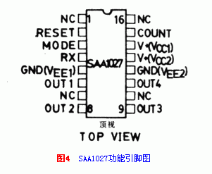
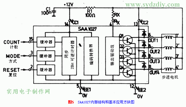
Four-phase stepper motors can use several special integrated circuit drivers. SAAl027 is one of the commonly used ones. It is characterized by a wide operating voltage range of 9.5V to 18V; a large output drive current, up to 500mA. It is suitable for the control of four-phase full-step stepping motor. Figure 4 is the appearance and pin function diagram of SAAl027. Figure 5 (below ↓) is its internal principle block diagram and basic application.
In fact, the integrated circuit has three buffered inputs, and each buffered input controls a two-bit (four-state) synchronous reversible counter. Its output is sent to a transcoder. Then use four outputs to control the four transistors of the output stage. The output stage works with an open collector. The winding coil of the motor is connected into the collector. In order to prevent the reverse electromotive force from damaging the transistor, a reverse diode is connected in parallel at both ends of the winding.
Special attention should be paid to: pins 13 and 12 of the integrated circuit are pins through which a large current flows. And 14 feet and 5 feet flow small current. When in use, pins 5 and 12 must be grounded. Usually plus 12V is directly connected to pin 13, and then to pin 14 via R1-C1 decoupling circuit. Positive voltage must also be sent to pin 4 via Rx. The role of Rx is to determine the maximum output drive current capacity of the four transistors. The size of Rx can be calculated by the following formula;
Rx ï¼ (4E ï¼ I) ï¼6
Where E is the power supply voltage and I is the desired maximum phase current of the motor. When using 12V, Rx value takes 420Ω, 180Ω or 78Ω), the maximum output current is 100mA, 200mA, or 350mA respectively.
SAA1027 integrated circuit has three input control terminals: counting, mode and reset. The reset terminal is usually high. Every time the counter changes from low to high, the integrated circuit will change state. All working conditions have been listed in Table 3.
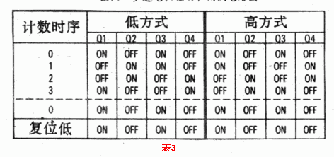
At any time, the sequence repeats every four steps. However, when the reset terminal is low, it can be reset to the initial state.
When the mode control input is low, the sequence repeats in one direction (usually clockwise rotation). Conversely, when the mode control terminal is at a high level, the sequence is repeated in the other direction (counterclockwise rotation).
Figure 6 is the drive and test circuit of SAAl027.
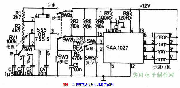
This circuit is used in a hybrid four-phase stepper motor with a rated current up to 300mA. The motor can be used for manual single-step test with SW3, or for automatic stepping test with SW2 via 555/7555 unstable oscillator. SW4 can control the direction of the motor. SW5 is used for reset control test.
With the SW1 and RV1 potentiometers, the working speed of the unstable circuit can be changed within a wide range. When set to 1st gear, it is low speed control, and the frequency range is from 5Hz to 68Hz. When SW2 is in 2nd and 3rd gears, the oscillation frequency is 10 times and 100 times of the 1st gear respectively. The total speed control range is from 6-8500 rpm.
Figure 6 is a basic circuit. According to different occasions, there are several changes.
Figure 7 is an interface circuit between a stepper motor and a microprocessor.
The output port of a computer or microprocessor is usually regarded as a logic 0 state when the terminal drive voltage is lower than 1V; and as a logic 1 state when it is higher than 3.5V. This logic is called positive logic. However, the circuit in Figure 7 is the opposite of the above. Therefore, when the input end of the stepping motor changes from high level to low level, the working state changes. The reset terminal is reset with a high level. When the mode input is low level, the motor rotates forward; when the level is high, the motor reverses.
The maximum output current of the circuit design in Figure 6 is 300mA.
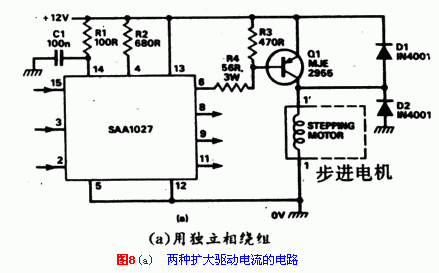
If you want to extend the current by 5A, use the two circuits in Figure 8. Each phase of the stepper motor requires an additional drive circuit, and a four-phase stepper motor needs to add four such additional circuits. The circuit in Fig. 8 (a) is used for the driving circuit. A four-phase stepper motor needs to add four such additional circuits. The circuit of Figure 8 (a) is used to drive four completely independent windings. The circuit of Fig. 8 (b) is used for stepping motors whose windings have a common point. The role of D1 and D2 is to prevent the back-EMF of the motor from damaging the output stage transistors.
Feyvan Electronics designs and manufactures NTC temperature sensors, probes, and cable assemblies with excellent long-term stability, high accuracy and short response time in high-temperature sensing applications such as automotive, home appliance and industrial use from -40℃ to +250℃.
With more than 15 years of NTC thermistors and sensor probes production experiences, Feyvan electronics provide various choices for a wide range of applications and are available in custom engineered probe package configurations for a variety of mounting and connectivity options with low costs.
Medical Equipment Sensor
Medical Equipment Sensor,Medical Sensor,Sensors Used In Healthcare,Medical Equipment Temperature Sensor
Feyvan Electronics Technology Co., Ltd. , http://www.fv-cable-assembly.com