Abstract: nRF902 is a monolithic RF transmitter chip, which contains frequency synthesizer, power amplifier, crystal oscillator and modulator and other circuits, can send digital signals. nRF902 adopts FSK modulation and can work in 868MHz ISM frequency band. The structure, principle, characteristics and application circuit of nRF902 are given in the article.
1 Overview
nRF902 is a monolithic transmitter chip with an operating frequency range of 862-870MHz in the ISM band. The transmitter consists of a fully integrated frequency synthesizer, power amplifier, crystal oscillator and modulator. Since nRF902 uses a crystal oscillator and a stable frequency synthesizer, the frequency drift is very low, which is completely comparable to the SAW resonator-based solution. The output power and frequency deviation of nRF902 can be programmed through external resistors. The power supply voltage range is 2.4 to 3.6V, the output power is 10dBm, and the current consumption is only 9mA. The power supply current in standby mode is only 10nA. The data rate when using FSK modulation is 50kbits / s. Therefore, the chip is suitable for alarm, automatic meter reading, home automation, remote control, wireless digital communication applications.
2 Pin function and structure principle
nRF902 is packaged in SIOC-8, and the functions of each pin are listed in Table 1.
Table 1 Pin functions of nRF902
| Pin end | Symbol | Features |
| 1 | XTAL | Crystal connection / PWR-UP control |
| 2 | REXT | Power adjustment / clock mode / ASK modulator word input |
| 3 | XO8 | Reference clock output (clock frequency 1/8) |
| 4 | VDD | Power supply voltage (+ 3V) |
| 5 | DIN | Digital data input |
| 6 | ANT2 | Antenna end |
| 7 | ANT1 | Antenna end |
| 8 | VSS | Ground (0V) |
Figure 1 shows the internal structure of nRF902, as can be seen from the figure: the chip contains a frequency synthesizer, power amplifier, crystal oscillator and modulator and other circuits.
The balanced RF signal can be output to the antenna through the nRF902 antenna output. This pin must also be connected to the power supply VDD through a DC channel. The power supply VDD can be accessed through the center of the RF choke or loop antenna. The load impedance between the output terminals of ANT1 / ANT2 is 200 ~ 700Ω. If an output power of 10dBm is required, a load impedance of 400Ω should be used. 
Modulation can be done by pulling the capacitance of the crystal. To achieve the specified frequency deviation, the characteristics of the crystal oscillator should meet: the parallel resonance frequency fp should be equal to the transmission center frequency divided by 64, the parallel equivalent capacitance Co should be less than 7pF, the crystal equivalent series resistance ESR should be less than 60Ω, all load capacitance, including The printed circuit board capacitance CL should be less than 10pF. Since frequency modulation is accomplished by pulling the load of the crystal (internal varactor diode), and the external resistor R4 will change the voltage of the varactor diode, therefore, changing the value of R4 can change the frequency deviation.
Connect the bias resistor R2 from the REXT terminal to the power supply terminal VDD to adjust the output power. The working mode of nRF902 can be set by the method listed in Table 2.
Table 2 nPF902 working mode settings
| Pin working mode | XTAL | REXT | XO8 | DIN |
| Low power mode (sleep mode) | GND | - | - | - |
| Clock mode | VDD | GND | VDD | - |
| ASK mode | VDD | ASK data | VDD or GND | VDD |
| FSK mode | VDD | VDD | VDD or GND | FSK data |
In FSK mode, the modulated data will be input from the DIN terminal, which is the standard working mode of nRF902.
ASK modulation can be achieved by controlling the REXT terminal. When R2 is connected to VDD, the chip transmits a carrier wave. When R2 is connected to ground, the power amplifier inside the chip is turned off. These two states can be represented by logic "1" and logic "0" in the ASK system. In ASK mode, DIN must be connected to VDD.
Clock mode can be applied to the case of an external microcontroller, nRF902 can provide a clock to the microcontroller. It can output the reference clock at the XO8 terminal, and the frequency of the clock signal output at the XO8 terminal is 1/8 of the crystal frequency. If the crystal frequency is 13.567MHz, the frequency of the clock signal output by XO8 is 1.695MHz.
In low-power mode (sleep mode), the current consumption of the chip is only 10nA. When there is no data transmission, the chip can work in low-power mode to extend the battery life. It takes 5ms for the circuit to switch from low power mode to transmit mode, and 50μs to switch from clock mode to transmit mode.
Figure 2 nRF902 application circuit
3 Application circuit design
The application circuit of nRF902 is shown as in Fig. 2. In order to obtain good RF performance, the design of the printed circuit board (PCB) is very important. It is recommended to use a minimum of two layers of PCB boards, including a ground plane. High-performance RF capacitors should be used close to the VDD terminal during design to complete DC power supply decoupling. It is recommended to use a large-capacity capacitor in parallel with a small-capacity capacitor between VDD and ground. The power supply voltage should also be sent from the power supply to each digital circuit after filtering. All device grounds, VDD connections, and VDD bypass capacitors must be as close as possible to the nRF902 chip. When the PCB uses the upper RF ground plate, the VSS terminal should be directly connected to the ground plate. When using a ground plane on the PCB, the best method is to connect to VSS through a via. Digital signal and control signal channels cannot be close to the crystal and XTAL terminals. The design of the printed board used by the author uses a double-sided 1.6mmFR-4 board. The bottom layer has a continuous ground plate, plus the ground area of ​​the component surface, thus ensuring a good ground. A large number of through holes can be connected from the ground plane of the component surface to the ground plane of the base plate, and there should be no ground plane under the antenna.
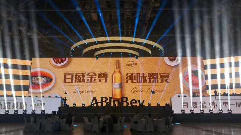
Outdoor Rental LED Screen description: in order to meet the requirements of all-weather performance and performance rental, outdoor LED mobile rental screen is particularly important. Its appearance makes up for the requirements that indoor LED mobile rental screen cannot achieve. Also compared with the traditional outdoor scenery, the grade is not high enough, the display content is single, affected by the environment, the wind is easy to deform, the heat is easy to change color and so on. Outdoor LED rental screen completely makes up for the shortage of traditional scenery.

Outdoor Mobile LED Display features:
1. The brightness is high. In outdoor mobile performance, the brightness is required to be more than 5000cd, otherwise the screen can not be seen clearly due to the influence of sunlight. The brightness of our outdoor performance screen is above 5000cd, which can be used all day.
2. It has strong UV resistance. It can be used outdoors for a long time due to the influence of sunlight. The lamp beads do not fade, but the color is still bright and the light is slow.
3. Outdoor LED mobile rental screen, with rain proof and dust-proof grade up to IP65, rain and wind are unimpeded, and rain proof cloth is used to prevent weather and rain.
4. The cabinet body adopts die-casting aluminum box structure, with good heat dissipation performance and high levelness.
5. For large-scale outdoor performance activities, the screen body can be shaped to form the same picture and split screen picture. For example, part of the screen shows the live content of the stage personnel, part of the screen shows the live broadcast of the audience, etc.
6. Brightness adjustment: according to the requirements of the use scene, the brightness can be adjusted, which greatly meets the requirements of different occasions. We are making perfect use of it both indoors and outdoors.

Outdoor Mobile Led Display Screen structure: quick lock structure, quick disassembly. The air plug and super-v network cable between the boxes can quickly link the signals and power supply between the boxes. The box has a waterproof rubber strip structure, which is waterproof up to IP65.
Precautions: as for indoor screen, pay attention to corners during handling and disassembly, handle with care, and cover the back cover for outdoor use to avoid water flow.
Outdoor Rental LED Screen
LED Display Rental,Rental Stage Led Display,Advertising Led Display,LED Video Screen For Rental
Shenzhen Vision Display Technology Co,.LTD , https://www.ledvdi.com