Multi-touch, as the name implies, recognizes the touch of two or more fingers. There are currently two types of multi-touch technology: MulTI-Touch Gesture and MulTI-Touch All-Point. In layman's terms, it is multi-touch recognition gesture direction and multi-touch recognition finger position.
1 Recognize gesture direction
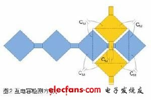
What we see most now is MulTI-Touch Gesture, that is, when two fingers touch, the movement direction of the two fingers can be recognized, but the specific position cannot be determined yet, and operations such as zooming, panning, and rotating can be performed. This multi-touch implementation is relatively simple, and the axis coordinate method can be implemented. Dividing ITO into X and Y axes can sense two touch operations, but the specific location of touch detection and touch detection are two concepts. The XY-axis touch screen can detect the second touch, but cannot know the exact position of the second touch. A single touch produces a single maximum value on each axis, thereby determining the location of the touch. If a second finger touches the screen, there will be two maximum values ​​on each axis. These two maximum values ​​can be generated by two sets of different touches, so the system cannot accurately judge. Some systems introduce timing to make judgments, assuming that two fingers are not placed at the same time, but there are always cases where they are touched at the same time. At this time, the system cannot guess. We can call the points that are not really touched as "ghost points", as shown in Figure 1.

MulTI-Touch All-Point is a relatively popular topic recently. It can identify the specific location of the touch point, that is, there is no "ghost point" phenomenon. The multi-touch recognition position can be applied to the detection of any touch gesture. It can detect the simultaneous touch of ten fingers of both hands, and also allows other non-finger touch forms, such as palm, face, fist, etc., even wearing gloves, it is the most The user-friendly human-machine interface is very suitable for applications where multiple hands operate simultaneously, such as game control. The scanning method of Multi-Touch All-Point is that each row and each column cross point needs to be scanned separately, and the number of scans is the product of the number of rows and the number of columns. For example, a touch screen composed of 10 row lines and 15 column lines uses Multi-Touch Gesture's axis coordinate method, and the number of scans required is 25, while the multi-touch recognition position method requires 150 times.
Multi-Touch All-Point is based on mutual capacitance detection method, not self-capacitance. Self-capacitance detection is the change of the capacitance of each sensing unit (that is, parasitic capacitance Cp). When there is a finger, the parasitic capacitance will increase to judge There is a touch, and mutual capacitance is to detect the change of the mutual capacitance (that is, coupling capacitance Cm) at the intersection of rows and columns. As shown in Figure 2, when the rows and columns cross, mutual capacitance will occur between the rows and columns (including: row and column sensing units Between the edge capacitance, the coupling capacitance generated at the intersection of rows and columns), the mutual capacitance will decrease when there is a finger, you can judge the presence of the touch, and accurately determine the location of each touch point.
The touch screen is introduced below. The touch screen is simply a combination of input and output, no need for mechanical buttons or sliders, and the display is the human-machine interface.
Multi-touch technology
Figure 3 shows a schematic diagram of a touch screen module. The entire module consists of an LCD, a touch screen, a touch screen controller, a main CPU, and an LCD controller. The touch screen and touch screen controller are the core of the entire module, so we will focus on these two parts.

Figure 4 from top to bottom are: 1 surface shield; 2 cover layer; 3 mask layer & marking layer; 4 optical glue; 5 first layer sensing unit and substrate; 6 optical glue; 7 second layer sensing unit With substrate; 8 air layer or optical glue; 9 LCD display.
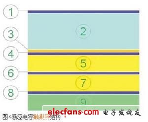
Surface shields are usually less than 100um thick. Hard shields are required on all plastic covers. This is because touching the fingers will scratch the plastic surface. If the cover is glass, a surface shield is not required, but the glass must be chemically strengthened or quenched. The surface shield needs to be covered with The layers are optically matched to avoid excessive light loss.
The cover layer can be 0 ~ 3 mm thick. Not all touch screens require a cover layer. The thinner the cover layer, the higher the signal-to-noise ratio and better sensing sensitivity. Common materials are: polycarbonate, plexiglass and glass.
The third layer is the mask layer and the marking layer, and its thickness is approximately 100 mm. The mask layer is located under the cover, which can hide the wiring and the edge of the LCD. Marking text or icons are allowed in the design, but the marker must be pressed on the ITO substrate fairly flat, and the marker material should be non-conductive.
The fourth layer is optical glue with a thickness of about 25 ~ 200mm. The thinner the optical glue, the better the signal-to-noise ratio. The high-permittivity (er) optical glue can better sense the capacitance of the finger, which can also obtain a higher signal-to-noise ratio. PSA pressure sensitive adhesives are usually used.
The fifth layer is the sensing unit and substrate. The thickness of the ITO coating is less than 100nm. The ITO coating substrate can be 100 um ~ 1mm glass (IR ~ 1.52) or 25mm ~ 300mm PET film (IR ~ 1.65). The thicker ITO, the lower the resistance per unit area, the better the signal-to-noise ratio; the thinner ITO, the better the light transmittance. The substrate may be thin film or glass. If ITO is made on the lower surface of the glass substrate, the glass substrate can be used as a surface covering.
The sixth layer is another layer of optical adhesive. Compared with the previous layer of optical adhesive, the thicker the layer of optical adhesive, the better the signal-to-noise ratio. This layer of optical adhesive is usually used in combination with ACA-anisotropic conductive adhesive. It is also the induction unit and the substrate, which are the same material as the first layer substrate. Note that the film and glass should not be mixed. If ITO is on the upper surface of the substrate, a thick substrate can obtain a higher signal-to-noise ratio; if ITO is on the lower surface of the substrate, a thin substrate makes the signal-to-noise ratio higher. It is also required to use anisotropic conductive adhesive in the edge area. There is now a single substrate process to simplify production and reduce costs.
The eighth layer is the layer of air or optical glue. We know that the dielectric constant of air is equal to 1, which can reduce the parasitic capacitance from the upper surface of the LCD. If you use optical glue, you can make the installation more robust. It is necessary to match the optical parameters to make the light loss smaller. It is necessary to select the optical glue with the lowest dielectric constant as possible, and to ensure that the distance between the ITO sensing unit and the upper surface of the LCD is at least 250 mm.
The last is the LCD screen. For the touch screen design, it is a noise source. The noise comes from the backlight. The LCD pixel drive control signal is usually not used. The passive dot matrix screen is not used. This will generate a high-voltage signal on the front of the LCD. Active dot matrix screen, which can constitute a virtual ground or shielding function; if you really need to use a passive dot matrix screen, you need to add an ITO shielding layer in the touch screen, the shielding layer must be grounded to remove the influence of parasitic capacitance CP.
2 Multi-touch screen controller
The multi-point touch screen controller is the core of the touch screen module. This article takes Cypress's touch screen controller as an example for introduction.
Cypress's touch screen controller is the Truetouch series, which is based on the widely used PSoC (Programmable System on Chip) technology. PSoC is a mixed signal array that integrates programmable analog and digital peripherals and MCU cores, so the flexibility, programmability, and high integration of PSoC are also applicable to Truetouch solutions.
The TrueTouch solution is a capacitive touch screen solution. The structure of this touch screen has been described above. It can be said that there are many manufacturers and types of LCD, and there are also many sensing devices, such as glass, thin film, ITO, etc., and even many models of ITO. Truetouch is based on PSoC technology, so the flexibility of PSoC makes it work well with many LCD and ITO.
Why is Cypress's touch screen controller named Truetouch scheme, or how did this "True" come from? Recalling the development of touch screens, from the beginning Single-touch—only one finger can touch or slide; later Multi-touch gesture also produced—the direction of two fingers can be recognized, but their specific positions cannot yet be determined , Can be zoomed, panned, rotated and other operations; developed to today-Cypress's True touch can achieve Multi-touch all-point, can recognize multiple fingers and determine the exact position, is a true multi-touch, this is also The origin of True.
Truetouch's product series can be divided into three categories, single-point touch, multi-touch gesture direction (multi-touch gesture) and multi-touch recognition position (multi-touch all-point). There are various models for each category, with differences in screen size, scanning speed, communication method, memory size, power consumption, etc., to meet different applications. The Truetouch series is based on PSoC technology, so these devices can be designed using the simple and convenient but powerful PSoC designer software environment.
The value of the TrueTouch solution is mainly reflected in the following aspects: maintaining the inherent beauty, lightness and thinness of the touch screen, which can make the customer's products stand out; adopting inductive capacitive touch screen technology, no mechanical devices are needed, and more durable; with a complete series, From single touch, to multi-touch recognition direction, to multi-touch recognition position; based on PSoC technology, flexible use, can be used with many LCD and ITO; all the value of PSoC can be reflected in Truetouch, such as flexible Performance, programmability, etc., can shorten the development cycle, make the product market quickly, and have a high degree of integration, you can integrate many peripheral devices into PSoC (that is, Truetouch products), which can not only reduce the system cost, but also reduce the overall Power consumption, improve power efficiency.
3 Conclusion
This article introduces multi-touch technology and touch screen and touch screen controller. It can be said that the touch screen is the final choice of the human-machine interface. Whether it is single-touch, multi-touch recognition direction, or multi-touch recognition location, they have obvious advantages in many applications, such as mobile phones, Mp3, GPS and so on. These products themselves are required to have the characteristics of small size and easy to carry. How to make the small size products play more functions depends on the application of the touch screen.
Slim Led Panel Light includes round and square two shape frame. This type of thin light body is ultra slim and easy to install. It is made by aluminum frame and iron back cover. We are the manufacturer of producing energy saving interior lighting. There are three color temperatures with cool white, warm white and natural white of panel lights. Besides it is adjustable among the three color temperatures. The unique feature of led Slim Panel Light is: CRI>80, PF>0.5. These panels are mainly apply to home, office and school, etc.
Slim LED Panel Light
Led Slim Panel,Slim Panel Light,Ultraslim Led Panel,Led Panel Ultraslim
Jiangmen Lika Lighting Electrical Appliances Co., Ltd , https://www.lika-led.com