Infrared thermal imager uses infrared detector, optical imaging objective lens and optical machine scanning system (the current advanced focal plane technology eliminates the optical machine scanning system) to receive the infrared radiation energy distribution pattern of the measured target and reflect it to the photosensitive element of the infrared detector Above, between the optical system and the infrared detector, there is an optomechanical scanning mechanism (the focal plane thermal imager does not have this mechanism) to scan the infrared thermal image of the measured object and focus on the unit or the spectroscopic detector. The detector converts the infrared radiation energy into an electrical signal, which is amplified and converted into a standard video signal, and the infrared thermal image is displayed on the TV screen or monitor. This thermal image corresponds to the thermal distribution field on the surface of the object. In addition to displaying infrared thermal radiation images, infrared cameras can also provide accurate non-contact temperature measurement functions.
From the first generation of thermal imaging cameras with scanning devices to condensing imaging infrared thermal imaging cameras with focal plane array structure, infrared thermal imaging cameras have developed from bulky, complicated operation to portable, hand-held devices that are lightweight, convenient and simple to operate.
The continuous development of high-performance processor chips has brought new impetus to thermal imaging cameras. With the appropriate processor, you can increase the speed of image processing and design more sophisticated products. This article discusses the design of an infrared camera based on an uncooled focal plane detector and a high-performance dual-core processor OMAPl510.
1 Hardware architecture
The signal of the thermal image distribution map of the infrared radiation of the target object to be measured is very weak. Compared with the visible light image, it lacks the layer and the three-dimensional sense. Therefore, in order to more effectively determine the infrared heat distribution field of the measured target during the actual detection process, some auxiliary measures are often used to increase the practical functions of the instrument, such as image brightness / contrast control, real standard correction, pseudo color rendering contour lines And directly perform mathematical operations, printing, etc.
The portable infrared thermal imager is mainly composed of an infrared camera with a 320 & TImes; 240 uncooled focal plane detector, a pre-processing unit, an OMAPl510 processor and its peripheral devices, as shown in Figure 1.
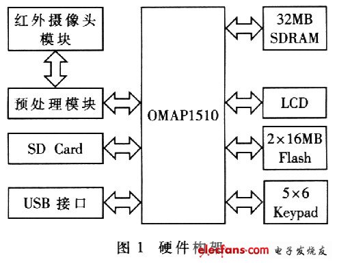
The 320 & TImes; 2AO image data collected by the infrared camera has a large amount of data. After the electrical signal converted from the detector is sampled, it first passes through a preprocessing module to convert the data into 16-bit data for processing by OMAPl510. 0MAPl510 needs to perform window level and window width processing, 256-color pseudo-color conversion, brightness contrast adjustment, etc. on the image data, and finally display it on the LCD screen of 320 & TImes; 240.
OMAPl510 processor is a high-performance single-chip dual-core processor produced by TI. It is mainly composed of TMS320C55x DSP core, low power consumption enhanced ARM925T. It is composed of microprocessor, traffic controller, powerful DMA controller and abundant peripheral equipment.
TI enhanced ARM925T core adopts ARM RISC architecture, and the main frequency is 175MHz. It includes a memory management unit, a 16KB high-speed instruction cache (Cache), an 8KB data cache, and a 17-word write buffer. There is 1.5MB of internal SRAM in the chip, which provides a large amount of data and code storage space for applications such as liquid crystal display. It has 13 internal interrupts and 19 external interrupts, using two-level interrupt management. In addition, there are ARM CPl5 coprocessors and protection modules in the core.
C55x DSP core has the best power consumption performance ratio, and the main frequency is 200MHz. It adds three hardware accelerators: discrete cosine transform, inverse discrete cosine transform accelerator, motion estimation arithmetic accelerator, and half-pixel interpolation accelerator. The C55x DSP core has 32K words of dual-access SRAN, 48K words of single-access SRAM, and 12K words of high-speed instruction cache. In addition, the core also contains a memory management unit (MMU), a two-level interrupt manager and a direct memory access (DMA) controller.
The traffic controller is the hub for data exchange between the ARM925T processor and each memory chip, and also controls the access of the DSP, DMA controller, and local bus interface to each memory. According to the characteristics of the off-chip memory, the traffic controller can flexibly configure the accessed word width, period, and burst access for whole-word access.
OMAPl510 chip has a wealth of peripheral interfaces, such as LCD controller, memory interface, camera interface, Bluetooth interface, universal asynchronous transceiver, I2C host interface, pulse width audio generator, serial interface, host client USB port, secure digital multimedia Card controller (SD / MMC) interface, keyboard interface, etc.
2 Software architecture
The software architecture is shown in Figure 2. The MPU is loaded with an embedded Linux operating system to realize the reading of front-end image data, access to LCD, touch screen, keyboard, SD card and other devices, communication with DSP, and operation of Qt application programs. The application program access to the LCD and other peripheral devices is implemented by the corresponding Linux driver. The MPU's access to the DSP also regards the DSP as a device, and implements the so-called DSP driver back-loading in the MPU. The DSP side constructs tasks for data processing on the basis of the DSP / BIOS, and performs arithmetic processing on the image data, such as window level and window width adjustment, pseudo-color search, brightness, and contrast adjustment.
There are three ways to implement communication between MPU and DSP: mailbox register, MPU interface and shared memory.
(1) MPU / DSP mailbox register MPU communicates with the DSP processor through the mailbox interrupt mechanism. In the public TIPB space, 4 mailbox register devices are shared by dual cores. Among them, 2 mailbox registers are used to let MPU send a message and send out the interrupt signal to DSP, the other 2 are used to let DSP send a message and send out the interrupt request signal to MPU. Each mailbox register device consists of two 16-bit registers and a l-bit flag register. The processor that issued the interrupt can use a 16-bit register to send a byte of data to the processor that received the interrupt, and another 16-bit register to send a one-word command.

When a processor writes the appropriate command word to the command register and generates an interrupt to another processor, the appropriate flag register is set, and communication is achieved. The processor receiving the interrupt confirms the interrupt by reading the command word and clearing the flag register. At this time, the data register in each mailbox register is valid and can transmit 2 words of data.
(2) MPU Interface (MPU)
MPUI allows MPU, system DMA controller to communicate with DSP and its peripherals. MPUI allows access to all DSP memory space (16MB) and public peripheral bus. Therefore, both the MPU and the system DMA controller have read and write access to the complete DSP I / O space (128KB), including the DSP-specific peripheral control registers.
(3) MPU / DSP shared memory
OMAP1510 implements a shared memory structure through the traffic controller (Traffic Controller). Therefore, both MPU and DSP can access the same shared memory SRAM (192KB) and EMIFF, EMIFS memory space. The MPU manages the memory through the DSP. The MMU determines which area of ​​the DSP is the shared memory that can be used for access. By allocating the shared memory area and defining the protocol for accessing the shared memory between the MPU and the DSP, the communication mechanism between the processors can be realized.
The communication between MPU and DSP of this system is realized by combining mailbox register and shared memory. Because the image data is large, and the mailbox register can only send 2 × 16 bits of data per communication, it is not possible to efficiently share large amounts of data using only the mailbox. Although shared memory allows MPU and DSP to share a section of memory. But there is no synchronization mechanism. Using mailbox registers to establish a handshake signal (interrupt), you can enable MPU and DSP to access shared memory synchronously. When the MPU writes the original data into the shared memory, it sends a message to the mailbox and sends an interrupt signal to the DSP to notify the DSP to process the data; when the DSP has finished processing the data, it also sends a message to the mailbox register and sends an interrupt signal to the MPU to notify The MPU data is ready.
During the test, it was found that the MPU and DSP will have a delay when communicating through the mailbox. When the amount of data and calculation is small, the efficiency of the dual-core mechanism is low; when the amount of data and calculation is large, the dual-core mechanism is far away More efficient than when using MPU only. The delay between MPU and DSP communication has little effect on the entire system. When the system dynamically displays 320 × 240, 16-bit image data, the DSP performs window level window width processing, pseudo-color look-up table, and converts the data into a 5-6-5 format that the LCD can receive, and the display rate is about It is 18 frames per second. When these operations are handed over to the MPU, the display rate is only 11.5 frames per second.
3 Qt application design
The GUIs for embedded systems are mainly MiniGUI, OpenGUI, MicomWindows, Ot / Embedded. This system uses Qt / Embedded.
Qt is a multi-platform C ++ graphical user interface toolkit developed by Troll Tech of Norway. It uses C ++ language and has the characteristics of object-oriented programming, so programs written in Qt are easy to understand and easy to maintain.
Qt / Embedded is an independent C ++ graphical user interface application platform development tool based on the Linux embedded platform with frame-buffer support. It contains a complete set of GUI classes, operating system packages, data structure classes, utilities, and comprehensive classes. It can directly write to the framebuffer to avoid users from using complex Xlib / Xserver systems. It provides all source code for embedded users and allows modification and further debugging. During the transplantation of Qt / embedded, when the device used (such as touch screen, keyboard) is not the standard control supported by Qt, the Qt / embedded source code needs to be modified to realize the response of the Qt program to the device.
The software flow of the image display part of the Qt application program of this system is shown in Figure 3. The user interface has a window style. Select different options from the main menu to pop up the corresponding function window: full screen display of infrared heat map; playback of the image saved on the memory card (BMP bitmap); delete the image and sense on the memory card Point of interest temperature display, etc. Click the exit button on the window to close the corresponding function window. The operation process can be completed either by pressing keys or by touching the touch screen. The entire GUI interface is simple in style and easy to operate.

In this paper, through the development and design process of portable infrared thermal imaging camera, the principle of uncooled infrared thermal imaging camera is explained, and the realization method of OMAPl510 handheld terminal is discussed. The performance indicators of the infrared thermal imager thus designed have reached a high level, such as high-speed dynamic imaging of infrared thermal images, picture storage to SD card, picture playback, USB port image transmission and other functions. Practice has shown that the dual-core 0MAP series is an embedded system chip with strong processing power, low power consumption and compact structure. It will show excellent characteristics in portable devices that require strong processing power.
Led Surface Panel Light,Direct-Lit Led Panel Lamp,Direct-Lit Led Panel Light,Surface Mounted Panel Light
Changxing Fanya Lighting Co.,Ltd , https://www.fyledlights.com