ZigBee is an emerging wireless sensor network communication technology with short distance, low power consumption and low transmission rate. With IEEE802.15.4 as the standard, the sensor nodes communicate with each other and relay the collected data to another network node or coordinator section in a relay manner. The technology uses the free IMS 2.4GHz, 915M and 868MHz frequency bands, the transmission rate is 20K to 250Kbps, with two-way communication function. It is suitable for occasions where the amount of communication data is not large, the transmission rate is relatively low, the distribution range is small, and the cost and power consumption are low.
With the widespread use of computer distributed processing, Internet and other technologies, the demand for computer networking has expanded rapidly. How to remotely manage the sensor network through the existing network infrastructure has gradually become a research topic for sensor networks and computer networks.
The wireless gateway design based on ZigBee and Ethernet is to build a data transmission channel between the wireless sensor network and the Internet.
In this design, the data transmission system converts the ZigBee data packets into Ethernet TCP / IP protocol data packets, which realizes the bidirectional transmission of data between the two protocols, builds a transparent transmission channel between the two, and completes the ZigBee technology. Communicate with Ethernet to realize on-site monitoring and remote control.
2 System Overview
The data transmission network system combining ZigBee and Ethernet includes ZigBee network and Ethernet. The ZigBee network transmits the collected data to the ZigBee junction in a multi-hop manner through the network node. The junction sends the data to the gateway. The gateway analyzes the ZigBee data packet, extracts valid information data from the data packet, and performs protocol conversion and data packet Repackaging and packaging into TCP / IP data packets, sending the data to the control center via Ethernet transmission, and completing the data transmission of the entire network. Figure 1 shows the data transmission network architecture combining ZigBee network and Ethernet.
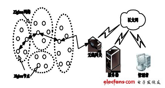
Figure 1 ZigBee and Ethernet data transmission network architecture
The gateway is a protocol converter built above the transport layer, connecting two independent networks of ZigBee and Ethernet, to achieve ZigBee and Ethernet protocol conversion, and compressing and packaging the data. It is converted into another data packet format without the need for additional protocol conversion devices to complete the protocol conversion and data transmission between the two. The structure of the gateway combining ZigBee and Ethernet can be abstracted from the structure diagram, as shown in Figure 2.
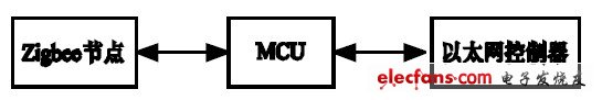
Figure 2 Gateway structure combining ZigBee and Ethernet.
3 Chip selection
3.1 ZigBee chip selection
The wireless transceiver chip CC2430 of Chengdu Chipcon Company was selected as the transmission scheme of this design ZigBee network.
CC2430 is a true system-on-chip, which integrates a high-performance 2.4GHz direct sequence spread spectrum (DSSS) RF transceiver core and an industrial-grade enhanced 8051 core [3], without the need to choose another processor, making the design simplify.
3.2 Selection of Ethernet chip
The network card chip RTL8019 from Taiwan's RETLTEK company is selected. This chip is highly integrated with ISA bus, which has the characteristics of low price, simple interface, no need for adapter chip, and strong compatibility.
4 Overall design
4.1 Hardware design
This design uses the 8051 core on the CC2430 chip as the MCU of the entire system to control the Ethernet chip RTL8019 to achieve ZigBee and Ethernet protocol conversion and data transmission. The hardware block diagram is shown in Figure 3:
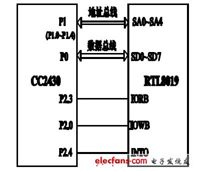
Figure 3 Block diagram of the hardware structure.
Because CC2430 only provides SPI bus and UART interface, the hardware interface does not choose another adapter chip and uses software simulation to solve the bus interface problem of address data, thus simplifying the hardware design of the system. The hardware interface adopts 8-bit data bus mode, and the data reading mode of RTL8019 on the ISA bus is selected by a jumper, so that RTL8019 works in 8-bit data bus mode.
4.2 Protocol conversion design
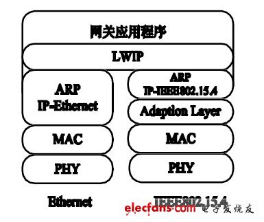
Figure 4 Block diagram of gateway protocol conversion.
In the TCP / IP protocol cluster, Ethernet data transmission uses a hardware address (MAC) to identify, where ARP (Address Resolution Protocol) completes the conversion between the IP address and the hardware address used by the data link layer [4] Therefore, in order to ensure the communication of ZigBee gateway in Ethernet, the function of ARP protocol must be realized first. All nodes in the ZigBee network have their own unique MAC addresses. Refer to the implementation mechanism under TCP / IP to implement the adaptation layer and ARP in the ZigBee protocol, and implement the mapping of IP addresses to ZigBee node addresses. The protocol conversion block diagram is shown in Figure 4. According to the figure, the process of data conversion from ZigBee to Ethernet is described: the ZigBee node in the wireless network receives the command and packages the data packet, sends it to the local ARP after simple judgment, and resolves the node through ARP Network MAC address, determine the Ethernet address to send to; then send it upward to the gateway application, after analysis, send it to the corresponding Ethernet UDP or TCP processing function for corresponding processing, and send it down to the Ethernet port MAC address. This completes the protocol conversion process from ZigBee to Ethernet.
4.3 Data transmission
The data packet sending process is shown in Figure 5: call the initialization function, initialize CC2430 and RTL8019, set the communication frequency and local address, call the radioSend (sendBuffer, sizeof, remoteAddrDO_NOT_ACK) function, determine the length of the data to be sent, locate the data to be sent The destination address, to determine whether it exceeds the maximum payload length allowed, otherwise the data is divided into several packets to send; then call the sppSend (& txData) function, the program is used to send the data packet pointed to by the data pointer. First set the DMA mode, prohibit the RF interrupt to add the format of the data packet to be sent (SPP_RX_STRUCT), the length of the loaded packet, the destination address, source address, flag and payload, open the acceptance confirmation link, and then send the data. If the setting requires confirmation, it will automatically switch to the acceptance state; if the maximum reception time of the set confirmation frame has not been accepted, the retransmission flag will be set; if the retransmission has not been accepted, it will report that the transmission has failed.
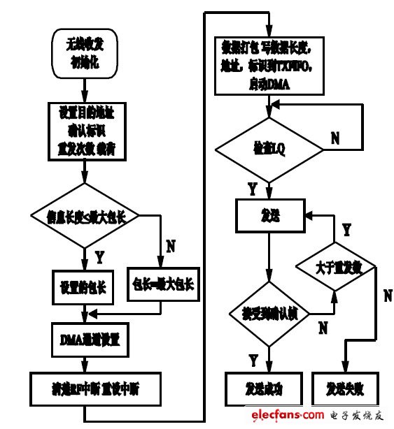
Figure 5 Flow chart of data packet sending.
5 Hardware circuit
The hardware circuit mainly includes CC2430 and RTL8019.
5.1 CC2430 hardware circuit
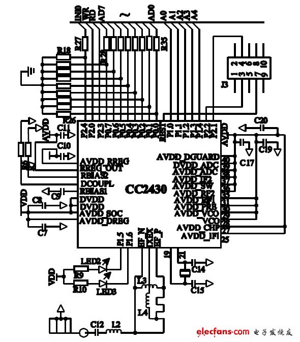
Figure 6 CC2430 hardware circuit diagram.
The CC2430 part is the wireless transceiver part of the ZigBee network, and uses a 32MHZ crystal to provide timing for the system. The circuit uses an unbalanced antenna. Connecting an unbalanced transformer can improve the natural reception performance.
The unbalanced transformer is composed of capacitor C12 and inductor L2, and meets the requirement of RF input and output matching resistance of 50 ohms.
The I / O ports provided by CC2430 are used as 8-bit data bus, address bus and control bus. The specific allocation is as follows: P0 port is used as 8-bit data port; the lower 5 bits of P1 port are used as address ports; P2.0 and P2.3 are respectively Used as a strobe signal for reading and writing; P2.4 port is used as an interrupt application signal line.
5.2 RTL8019 hardware circuit
RTL8019 is responsible for converting ZigBee data packets into TCP / IP data packets. A 20M crystal oscillator is used in the circuit to provide working timing. The local DMA interface connects the network card chip and the network cable to complete the data exchange between the controller and the network cable.
Working mode: The 65th pin JP of RTL8019 determines the working mode of the network card chip, and the high level is the jumper working mode.
I / O port: The 81, 82, 84, and 85 pins of the RTL8019 determine the I / O port address, all are floating in the design, and the selected address is 0300H.
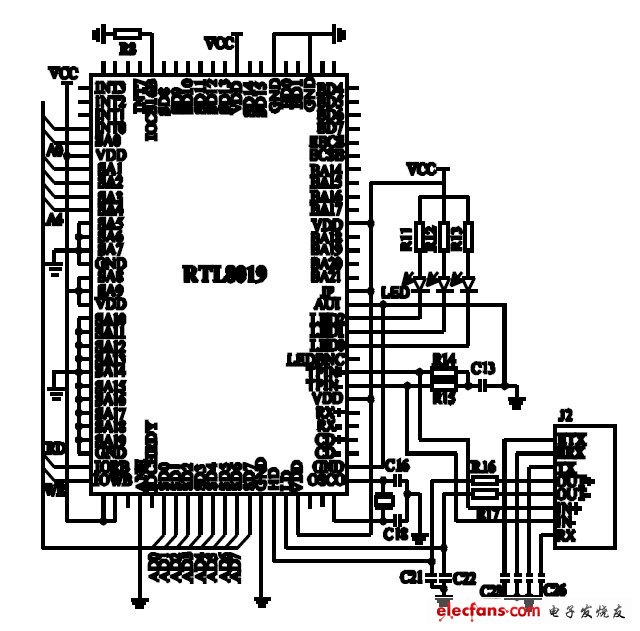
Figure 7 RTL8019 hardware circuit diagram.
Network interface: Determined by the 74 and 77 pins of the RTL8019, use automatic detection, 64 pins are low level, use the BNC interface.
Interrupt: The 78, 79, 80 pins of RTL8019 determine the interrupt mode of the chip. All are suspended in the design, and the selected interrupt is INT0.
6 Conclusion
The gateway has low power consumption, small size and simple design, which can meet the requirements of small data volume. Building a bridge between ZigBee short-range wireless communication and Ethernet remote data transmission provides an Ethernet network platform for ZigBee sensor networks, making ZigBee more widely used in wireless sensor networks.
TECHNOLOGY
WHAT IS AN Air Purifier?
Breathing clean air is very important.
It is scientifically proven that the air in our homes contains allergens(pollen ,mites ,moulds ,etc ).
noxious substance, bacteria viruses and suspended smells.
We have the solution for it!
• Small and medium sized spaces, Desktop Air Purifier, Air Cleaner
• Removes 99% of fine dust , mold , allergens and viruses
• Fan speed: Low , Normal , High
• HEPA filter air purifier can reduce pollen , dust , dander , smoke , pollution , viruses , bacteria and mold spores
•
• Filter replacement indicator
• UV lamp
• Optional HEPA H13
• HEPA filter air purifier can reduce pollen , dust , dander , smoke , pollution , viruses , bacteria and mold spores
• UVc lamp kill viruses like COVID-19
• Best air purifier for kid`s room
We care for your air
Hepa Air Purifier For Dust,Hepa Air Purifier For Kid,Hepa Air Purifier,Hepa Air Purifier For Home
Ningbo Zhe Kai Electric Appliance Co.,Ltd , https://www.cnairpurifiers.com