The smart toilet cover originated in the United States and is used for medical and geriatric care. It was originally equipped with a warm water wash function. The United States first began to manufacture smart toilet seats. After South Korea, Japanese sanitary ware companies gradually introduced technology to manufacture.
Japan introduced a new product in the 1980s, adding a variety of functions such as lid heating, warm water washing, warm air drying, and sterilization.
In the toilet revolution held in South Korea in the 1980s, the state invested a lot of money to develop smart toilet seats. The use of homes in Korea accounts for 20%, and more and more groups in Japan are using smart toilets.
Only 0.1% of households in China use smart toilet lids, because the promotion of smart toilet lids in the Chinese market only begins with initial and broad prospects.
Smart toilet lids on the market generally include the following: one is a smart toilet lid with cleaning, heating, and the like. The other is a smart toilet lid that automatically replaces the film. There is also a toilet cover which is a smart toilet cover with a sanitary napkin for automatically replacing a disposable seat cushion. The sanitary sleeve is a disposable sanitary napkin which conforms to the food packaging inspection standard (like a household plastic wrap), and the smart toilet cover passes. The built-in microcomputer controller automatically replaces the sanitary film (the sanitary film cover rotates exactly one seat), and the used film is cut and destroyed during recycling, which is clearly distinguished from the unused sanitary film and achieves the purpose of non-reusability. Eliminate the possibility of cross-contagion, its function is tangible, health is visible, this is the characteristics of the smart toilet cover, but also the function that ordinary toilet seat cushion can not achieve. There is another type of smart toilet cover that is replaced by a cleaning and cleaning device, that is, a sanitary toilet cover with a sanitary film, a flushing, and a function of sterilization, deodorization, music, and the like.
Many consumers are worried that they can't pick a good toilet cover in China. In fact, in recent years, domestic smart products have been continuously improved in technology, and they are more in line with the habits of Chinese people.
Recommended reading: With this Moye board toilet cover can become a wireless charging board
Smart toilet pick up sensor application boom
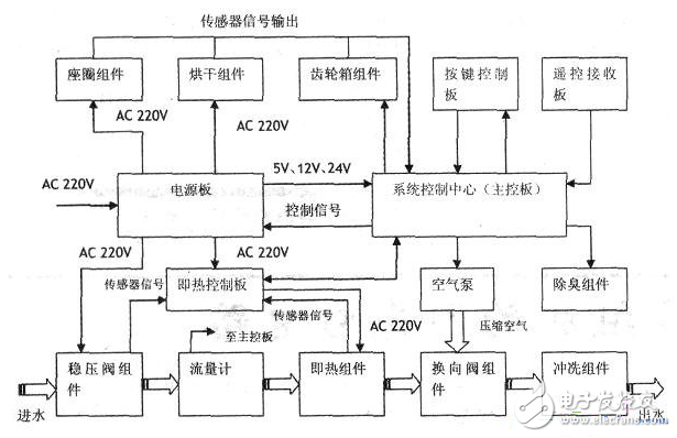
The electronic toilet seat system block diagram is shown in the following figure. The electronic toilet cover can be divided into three parts: waterway, circuit control, mechanism and heater components.
1. Waterway section
The waterway portion is composed of a pressure regulating valve assembly, a flow meter, that is, a heat assembly, a reversing valve assembly, an air pump, and a flushing assembly. The components and functions of each component are described below.
(1) Regulator valve assembly
The regulator valve assembly consists of a copper connector, a solenoid valve, and a regulator valve.
The copper connector is used to connect the inlet pipe and the pressure regulator; the solenoid valve controls the inflow of water; the pressure regulator keeps the water output pressure stable. When the inlet static pressure is 2kgf/cm 2 or 8kgf/cm 2 , the outlet pressure is stable at 0.7±0.1kgf/cm 2 .
(2) Flow meter
It is mainly used to monitor the flow, and the result is sent to the MCU and MCU in pulses, and then according to different flow control, the hot component heats the water with the corresponding power.
(3) Instant components
Mainly composed of ceramic heating tube, temperature control switch, temperature sensor, water level switch and instant body.
Main function: heat the cold water to reach the set temperature and control the water temperature. After 15 s of effluent is required, the water temperature reaches 40 °C ± 1 °C, and the temperature fluctuation is within 2 °C for 1 min.
Among them, the ceramic heating tube is used for heating water, and its maximum power is controlled at 1520W~1680W; the temperature sensor detects the water temperature and sends it to the MCU: the water level switch is used to prevent the heating tube from dry burning; the function of the temperature control switch is when the temperature exceeds 55°C Disconnect the power supply from the heating tube to prevent damage caused by excessive water temperature.
(4) Air pump
Its function is to provide compressed air to the valve to make the water and air mix together, increase the cleaning force and improve the cleaning cleanliness. Some models do not use an air pump, which can be judged by the sound of a hip wash or a woman wash water spray: a "beep" sound when spraying water indicates that an air pump is installed, and vice versa.
(5) Reversing é—½ component
Its function is to switch the hip wash and the woman's wash, and mix the waterway with the air; the second is to control the flow of the hip wash or the woman wash. The advantages and disadvantages of this device directly affect the function switching and flow, which is a very important component with high precision requirements.
(6) Flushing components
The rinsing assembly is mainly composed of a motor, a gear set and a nozzle group. The working principle is that the motor drives the gear set to engage with the rack in the nozzle assembly, so that the nozzle assembly can make a reciprocating motion, thereby realizing the flushing function and the moving massage function.
2. Circuit control section
The circuit control part is composed of a power board, a main control board, that is, a thermal control board, a keypad, and a keypad.
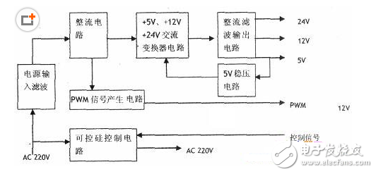
(1) Power board
A switching power supply circuit is used. Its main function, one is to provide +5V, +12V, +24V DC voltage and PWM signal to the main control board: Second, through the thyristor control device on the board to the seat heater, water inlet solenoid valve, drying and heating The device provides 220V AC voltage.
The circuit block diagram is shown below. AC220V mains filters high frequency clutter through the power input filter circuit. Then, it is rectified and filtered to obtain a DC voltage of 300V. Then through the +5V, +12V, +24V AC converter circuit composed of the electric switching converter, the switch tube and the IC chip, the required pulse AC voltage is generated in the secondary of the switch; finally, the rectifier circuit and the filter circuit generate +5V, +12V and +24V DC voltage. +5V is mainly for system control circuit and general circuit power supply, +12V for dry motor, deodorizing motor, flushing motor, reversing valve motor and air pump motor and alarm circuit, +24V for automatic flip motor. The +5V uses a secondary sampling regulator.
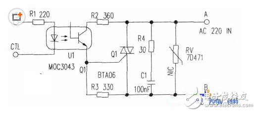
There are two special circuits in the power circuit, one is the thyristor control circuit, and the other is the PWM generation circuit. The following figure shows the thyristor control circuit of a branch. The CTL signal comes from the MCU. The signal is controlled by the optocoupler U1 (MOC3043) to control the bidirectional thyristor Q1 to control the AC input from the A terminal. End output. R4 and Cl are protection circuits of Q1.
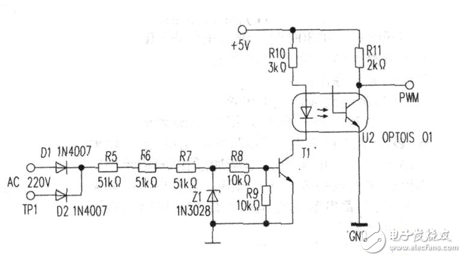
The figure below shows the PWM generation circuit. AC220V mains is rectified by Dl and D2, R5, R6 and R7 are divided and Zl is regulated. 22V ripple voltage is generated at Z1 cathode. The voltage is divided by R8 and R9, triode T1 is driven, and optocoupler U2 (OPTOISO1) is controlled. The phototransistor output in the optocoupler changes with the intensity of the light, thereby forming a PWM signal for use by the main control board MCU.
(2) main control
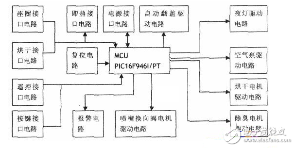
The board main control board is the control center of the system. The single-chip microcomputer PIC16F946I/PT controls the thyristor, nozzle reversing valve motor, air booster pump, nozzle swing motor, drying motor, deodorizing motor, automatic flip cover, seat ring and alarm buzzer. The main control board also includes the drive circuit of the above device. The following figure is the block diagram of the main control board circuit.
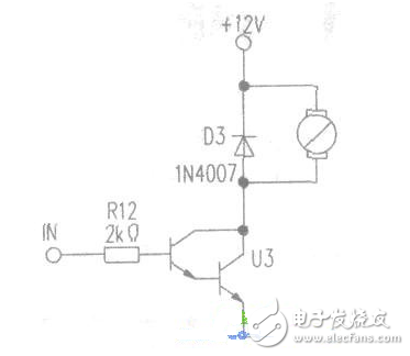
The figure below shows a typical drive circuit, which is mainly used to control the rotation of the motor through the U3 drive tube. When inputting a high level, U3 is turned on and the motor rotates; when a low level is input, U3 is turned off and the motor stops.
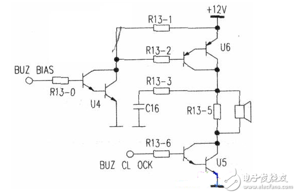
The following figure shows the alarm circuit. The buzzer amplifier circuit is composed of U4, U5, U6 and related bias circuits.
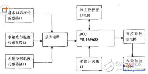
(3) Thermal control board
That is, the thermal control board is used to control the heating time and power of the ceramic heating tube in the printing heat assembly, and the water temperature in the hot water tank is controlled to meet the needs of the user. The main chip used is also the single chip PIC16F688. The following figure shows the block diagram of the thermal control board. The system collects the temperature information through three temperature sensors and converts it into a voltage value. After amplification, it is sent to the single-chip microcomputer, which judges and outputs the control signal to the thyristor control circuit. Finally, the thyristor control circuit controls the ceramic heating tube. To achieve the desired water temperature.
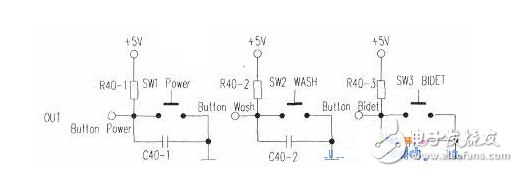
(4) button board
The keypad consists of a button and a status display LED. The main buttons are power supply POWER, hip wash WASH and bake wash BIDET. The button circuit shown below shows the functions of booting, hip washing and women washing.
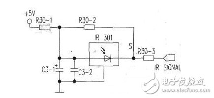
(5) Remote control receiver board
The remote receiving board receives the infrared signal from the remote control and transmits its digital signal to the MCU. The figure below shows the infrared receiving circuit and the IR301 is the remote receiving head.
3. Mechanism and heater section
(1) Seat assembly
The seat assembly is mainly composed of a cover plate, a heater, a temperature sensor, a temperature fuse, a human body sensor and a seat ring. Its main function is to heat the seat, the power is 48W ~ 53W. The race temperature is generally controlled at 37 ° C ± 3 ° C. The human body sensor is used to ensure that the flush switch does not start before the person is touched, and there is no need to worry about the danger caused by the wrong switch.
(2) drying components
The drying assembly is mainly composed of a blower, a mica heater, a temperature sensor and a duct cover.
Its main function is to generate hot air by means of a blower by energizing the heater, and the power is 300W~400W.
(3) Gearbox assembly
The main function is automatic flip cover, which consists of DC motor, worm, upper cover gear, three-layer gear, upper cover shaft, double gear limiter and helical gear.
(4) Deodorizing components
It is mainly composed of activated carbon and suction fan, which is used to eliminate the odor in the activated carbon to achieve the deodorizing function.
4. How the system works
Press the POWER button, the system opens the water inlet solenoid valve, and the tap water is regulated by the voltage regulator component and then enters the flowmeter, that is, the self-cleaning water branch of the heat component and the reversing valve component to the flushing component, and automatically cleans the nozzle of the flushing component. When the WASH button is pressed, the system warms the water according to the set temperature, the reversing valve switches to the hip washing branch, and then drives the flushing component motor to extend the nozzle to realize the hip washing function; when the BIDET button is pressed The process is the same as the hip wash. The difference is that the reversing valve is switched to the bide wash branch. After use, you can press the drying button to dry or deodorize the deodorizing button. The system can also realize automatic flip cover, seat heating and other functions according to the settings.
Related reading: Microwave sensing technology application for smart toilets
China Smart Distribution Box,Electrical Smart Cabinet manufacturer, choose the high quality Smart Electrical Distribution Box,Electrical Cabinet Smart Distribution Box, etc.
Through the 24-hour continuous monitoring of the equipment, the Intelligent Monitoring Box can view the online status of each equipment on the intelligent monitoring cloud platform. It can accurately distinguish the types of mains, network, and equipment failures, and can detect abnormalities and failures of the mains. Monitoring of faults such as voltage, undervoltage, leakage, and illegal access to electricity, and the equipment is equipped with a GPS positioning system. Once the equipment fails, the location of the equipment failure can be accurately located.
The intelligent monitoring box can adopt multiple status detection mechanisms of front-end power supply failure, network failure, traffic failure plus back-end cloud platform confirmation to provide the back-end with alarm accuracy. Once the equipment has the above failures, the back-end cloud platform can quickly alert and prompt the cause of the equipment failure. In addition, the cloud platform uses clustering algorithms, root cause analysis and other algorithms to perform big data and multi-dimensional analysis to improve the effectiveness of alarms and greatly reduce troubleshooting time.
Smart Distribution Box,Electrical Smart Cabinet,Smart Electrical Distribution Box,Electrical Cabinet Smart Distribution Box
Shenzhen Scodeno Technology Co.,Ltd , https://www.scodenonet.com