First, the fault characteristics and maintenance of the industrial control circuit board capacitor damage
Faults caused by capacitor damage are highest in electronic devices, with electrolytic capacitors being the most common.
The damage of the capacitor is as follows: 1. The capacity becomes smaller; 2. The capacity is completely lost; 3. The leakage occurs ; 4. The short circuit.

Capacitors play different roles in the circuit, and the resulting faults also have their own characteristics. In the industrial control circuit board, digital circuits account for the vast majority, and capacitors are often used for power supply filtering, and the capacitance used for signal coupling and oscillation circuits is less. If the Electrolytic capacitor used in the switching power supply is damaged, the switching power supply may not vibrate and there is no voltage output; or the output voltage is not well filtered, the circuit is logically confusing due to voltage instability, and the performance is good or bad when the machine is working. If the capacitor is not between the positive and negative terminals of the digital circuit, the fault will be the same as above.
This is especially obvious on the computer motherboard. Many computers have been used for a few years, sometimes they can't be turned on, and sometimes they can be turned on. When you open the case, you can often see the phenomenon of electrolytic capacitor drums. If you remove the capacitor, measure the capacity. It was found to be much lower than the actual value.
The life of a capacitor is directly related to the ambient temperature. The higher the ambient temperature, the shorter the capacitor life. This rule applies not only to electrolytic capacitors, but also to Other Capacitors. Therefore, when looking for faulty capacitors, it is important to check the capacitors that are close to the heat source, such as the capacitors next to the heat sink and the high-power components. The closer to them, the greater the possibility of damage.
I once repaired the power supply of an X-ray flaw detector. The user reflected that smoke had emerged from the power supply. After disassembling the chassis, I found that a large capacitor of 1000uF/350V had oily things flowing out and removed a certain amount of capacity. Only a few tens of uF, it is found that only this capacitor is closest to the heat sink of the rectifier bridge, and the other distances are intact and the capacity is normal. In addition, there is a case where the Ceramic Capacitor is short-circuited, and it is also found that the capacitor is relatively close to the heat-generating component. Therefore, there should be some emphasis when looking for repairs.
Some capacitors are more likely to leak, and they may even be hot when touched with a finger. This capacitor must be replaced.
In the case of a good or bad fault during maintenance, the possibility of poor contact is ruled out, and most of them are faults caused by capacitor damage. Therefore, when encountering such a fault, you can check the capacitance carefully. It is often surprising to replace the capacitor (of course, pay attention to the quality of the capacitor, choose a better brand, such as ruby, black diamond, etc.).
Second, the characteristics and discrimination of resistance damage
It is often seen that many beginners toss on the resistance when repairing the circuit, and it is also disassembled and welded. In fact, it is much more repaired. As long as you understand the damage characteristics of the resistor, you don't have to pay much attention.

Resistance is the most abundant component in electrical equipment, but it is not the component with the highest damage rate. Resistance damage is the most common with open circuit, the resistance value becomes smaller, and the resistance value becomes very small. Common carbon film resistors, Metal film resistors, wirewound resistors and fuse resistors.
The first two resistors are the most widely used, and their damage characteristics are low resistance (less than 100Ω) and high resistance (above 100kΩ), and high resistance, intermediate resistance (such as several hundred ohms to several tens of kilo ohms). Very little damage; second, the low resistance value of the resistor is often burnt black, it is easy to find, and the high resistance resistor has few traces when it is damaged.
Wirewound resistors are generally used as current limiting currents with little resistance. When the cylindrical wirewound resistor is burnt out, some may be black or have a surface blast, crack, and some have no trace. Cement resistance is a kind of wirewound resistor that may break when burnt out, otherwise there will be no visible traces. When the fuse is burned out, some surfaces will blow up a piece of skin, and some will have no trace, but it will never burnt and black. According to the above characteristics, when checking the resistance, you can focus on it and quickly find out the damaged resistance.
According to the characteristics listed above, we can first observe whether there is any black mark on the low-resistance resistance of the circuit board, and then according to the characteristics that most of the open circuit or resistance value becomes large and the high resistance value is easily damaged according to the resistance damage, We can use the multimeter to directly measure the resistance of the high-resistance resistor on the circuit board. If the resistance is larger than the nominal resistance, the resistor will be damaged (note that the resistance value is stable after the resistance is displayed. In conclusion, because there is a possibility that the capacitor is connected in parallel in the circuit, there is a charge and discharge process. If the resistance is smaller than the nominal resistance, it is generally ignored. In this way, each resistor on the board is measured once, even if "missing" a thousand, it will not let go.
Third, the operational amplifier is judged by good or bad
The judgment of the operational amplifier is difficult for a considerable number of electronic maintenance personnel, not only the degree of education (there are many undergraduates under the teacher, if you don’t teach, you will definitely not, and it will take a long time to understand, and there is a special The postgraduate of the instructor's frequency control is actually the same!), I would like to discuss with you here, I hope to help everyone.
Ideal op amps have "virtual short" and "dummy" characteristics that are useful for analyzing linearly used op amp circuits. To ensure linear operation, the op amp must operate in a closed loop (negative feedback). If there is no negative feedback, the op amp under open loop amplification becomes a comparator. If you want to judge the quality of the device, you should first distinguish whether the device is used as an amplifier or a comparator in the circuit.
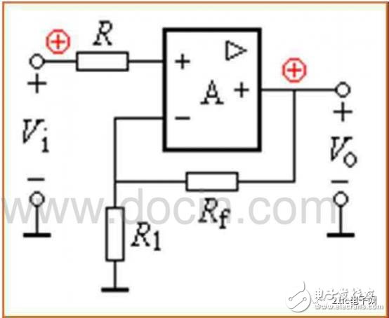

From the figure we can see that no matter what type of amplifier, there is a feedback resistor Rf, we can check this feedback resistor from the circuit during maintenance, check the resistance between the output and the reverse input with a multimeter Value, if the large is outrageous, such as a few MΩ or more, then we can probably be sure that the device is used as a comparator. If the resistance is smaller than 0Ω to tens of kΩ, then check whether there is a resistor connected to the output and the reverse input. Between the ends, there is something to be used as an amplifier.
According to the principle of the virtual short of the amplifier, that is, if the operational amplifier works normally, the voltages of the same input and the reverse input must be equal, even if there is a difference, the mv level, of course, in some high input impedance circuits, the multimeter The internal resistance will have a little influence on the voltage test, but generally it will not exceed 0.2V. If there is a difference of 0.5V or more, the amplifier will be bad! (I am using the FLUKE179 multimeter)
If the device is used as a comparator, the same direction input and the reverse input end are allowed to be unequal. The same direction voltage > reverse voltage, the output voltage is close to the positive maximum value; the same direction voltage < reverse voltage, the output voltage is close to 0V or negative maximum (depends on dual power supply or single power supply).
If the detected voltage does not meet this rule, the device will be bad!
This way you don't have to use the substitution method to judge the operational amplifier's quality without removing the chip on the board.
Fourth, a small test of the multimeter test SMT components
Some patch components are very small, and it is inconvenient to test and repair with a common multimeter pen. First, it is easy to cause short circuit. Second, it is inconvenient for the circuit board coated with the insulating coating to contact the metal part of the component pin. Here is a simple way to tell you a lot of convenience.
Take the two smallest needles, (deep industrial control technology column) and close it with the multimeter pen, then take a thin copper wire in a multi-strand cable, and tie the test leads and the sewing needle with a thin copper wire. Together, solder with solder. In this way, when the SMT components are tested with a small needle tip, there is no short circuit, and the needle tip can pierce the insulating coating and directly smash the key parts, and no need to bother to scrape the film.
Five, the circuit board public power supply short circuit fault repair method
In circuit board maintenance, if a short circuit of a common power supply is encountered, the fault is often large. Because many devices share the same power supply, each device using this power supply is suspected of being short-circuited. If there are not many components on the board, use "锄地" In the end, the short-circuit point can be found. If there are too many components, it is up to luck to "get the earth". Here, we recommend a method of comparing and using. This method is used to get twice the result with half the effort, and often finds the point of failure very quickly.
It is necessary to have a power supply with adjustable voltage and current, voltage 0-30V, current 0-3A, this power supply is not expensive, about 300 yuan. Adjust the open circuit voltage to the device power supply voltage level, first adjust the current to the minimum, add this voltage to the power supply voltage point of the circuit, such as the 5V and 0V terminals of the 74 series chip, depending on the degree of short circuit, slowly increase the current. When the hand touches the device, when a certain device is heated, this is often a damaged component, which can be removed for further measurement confirmation. Of course, the voltage must not exceed the operating voltage of the device during operation, and it cannot be reversed, otherwise it will burn out other good devices.
Six, a small rubber, solve big problems
There are more and more boards used for industrial control. Many boards use gold fingers to insert slots. Due to the harsh industrial environment, dusty, humid, and corrosive gas environments can cause poor contact failure. A friend may solve the problem by replacing the board, but the cost of purchasing the board is very considerable, especially for some imported equipment. In fact, you may wish to use the eraser to rub a few times on the gold finger, clean the dirt on the gold finger, and then try the machine, the problem may be solved! The method is simple and practical.
VII. Analysis of good and bad electrical faults
The various types of good and bad electrical faults may include the following in terms of probability:
Poor contact
Poor contact between the board and the slot, unreachable when the cable is broken inside, poor contact between the line plug and the terminal, and solder joints of the components are all such;
2. Signal interference
For digital circuits, under certain conditions, the fault will be presented. It may be that the interference is too much, which affects the control system to make errors, and the individual component parameters or overall performance parameters of the board have changed, so that the interference is prevented. The ability tends to a critical point, causing a failure;
3. The thermal stability of the components is not good
From the perspective of a large number of maintenance practices, the thermal stability of the first electrolytic capacitor is not good, followed by other capacitors, transistors, diodes, ICs, resistors, etc.
4. There is moisture, dust, etc. on the circuit board.
Moisture and dust will be conductive, have a resistance effect, and the resistance will change during the process of thermal expansion and contraction. This resistance value will have parallel effect with other components. When this effect is strong, the circuit parameters will be changed to make the fault. occur;
5. Software is also one of the considerations
Many parameters in the circuit are adjusted using software. The margin of some parameters is adjusted too low and is in the critical range. When the machine operating condition meets the reason for the software to determine the fault, the alarm will appear.
How to quickly find component data
Modern electronic products are diverse, and the types of components are increasing. It is more than a thousand. In circuit maintenance, especially in the field of industrial circuit board maintenance, many components are unheard of, or even unheard of, and even if the components of a board are complete, However, in the computer, the information should be read and analyzed one by one. If there is no quick search method, the maintenance efficiency will be greatly reduced. In the field of industrial electronic maintenance, efficiency is money. If the efficiency is too low, it will not be able to go with the pocket money.
We should be grateful to be born in this great era. The Internet is far from being boundless, making every corner of the world seem to be within reach. Free information is everywhere, and everyone can reach out and welcome. So everyone must make good use of the powerful tool of the Internet to make it easier for you!
Finally, recommend a product for everyone.
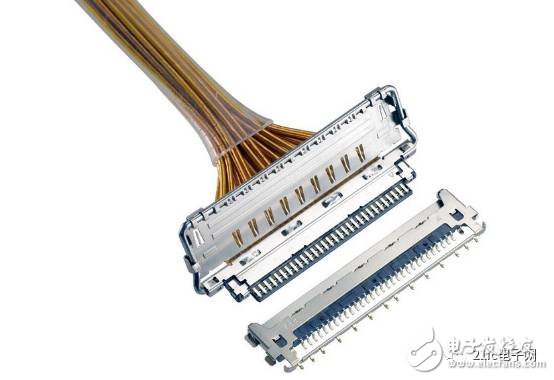
Compared to the 2009 VESA standard connector, the I-PEX Connectors SB II ultra-fine coaxial cable connector from the CABLINE series is an extension of the CABLINE series. High-speed contact design, up to 20 Gbps data transfer rate, supporting the latest Thunderbolt 3 and IoT applications.
The new CABLINE-VS II connector features a 360-degree fully shielded construction that provides more efficient EMI control at an overall height of only 1.3 mm max. In addition, the VESA standard connector - CABLINE-VS's female base can be mounted on the same design PCB.
CABLINE-VS II is 0.5 mm pitch, horizontal butt, 30 pins (40 pin version is coming online)
The new connector's high-speed data transfer performance and omni-directional shielding construction completely liberate designers, allowing them to focus on delivering innovative solutions.
Diode Module
Diode module is called silicon stack, it is made from several diodes in series, the number of the diode is by its highest pressure (maximum) negative peak pressure, main purpose is for high voltage rectifier. China Diode Module,High Voltage Diodes supplier & manufacturer, offer low price, high quality Caterpillar Diode Module,High Frequency Diode Module, etc.
Diode Module,High Voltage Diodes,Caterpillar Diode Module,High Frequency Diode Module
YANGZHOU POSITIONING TECH CO., LTD. , https://www.cndingweitech.com