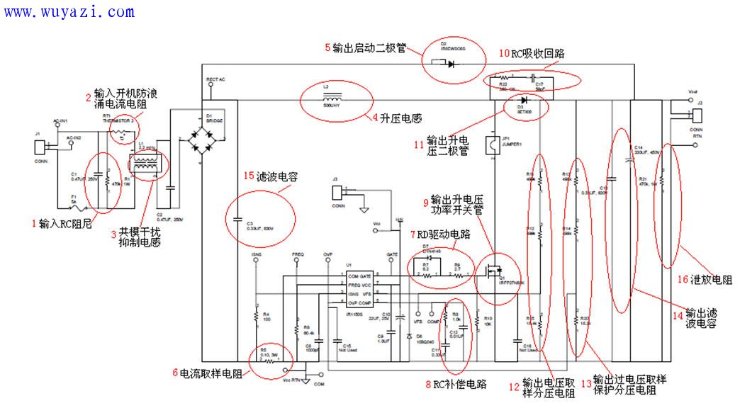
1. Start with an input surge current limiting resistor to protect the circuit from sudden voltage spikes. This component helps regulate the initial inrush of current when the system is turned on.
2. Implement a flow-by-flow passive power factor correction (PPFC) circuit to enhance the power factor of the system. By increasing the conduction angle of the AC input rectifier diode, this approach improves efficiency and reduces harmonic distortion. The PPFC method is cost-effective and suitable for low-power applications.
3. A filter capacitor is used to smooth out the rectified AC input. When the AC voltage approaches zero crossing, the energy stored in the capacitor C3 is used to power the IC, which is typically a high-voltage power supply IC designed for such applications.
4. Oscillation control is managed through a resistor connected between the oscillator pin and ground, which determines the PWM frequency. By connecting the ROSC pin between the external MOSFET gate and an external oscillation resistor, the IC can switch to a constant off-time (PFM) mode, improving efficiency under light load conditions.
5. The LED string and external MOSFET switch Q1 are monitored via a current-sensing resistor. If the voltage across RSENSE exceeds the threshold of the current sense pin (CS), the MOSFET Q1 turns off. This action allows the energy stored in the inductor to continue powering the LED load through the freewheeling diode D1.
6. The BUCK conversion power switch Q1 plays a key role in regulating the DC output. The AC mains rectified output DC voltage passes through the load, inductor L1, and the BUCK switch Q1, along with the current sensing resistor RSENSE, to form a closed loop. When Q1 turns off, the magnetic energy stored in the inductor continues to supply power to the load through the freewheeling diode D1.
7. When the BUCK switch Q1 is turned on, the rectified AC voltage flows through the load and the inductor L1, storing energy in the inductor. Once Q1 is turned off, this stored energy is released to power the load, ensuring continuous operation.
8. An output filter capacitor stabilizes the voltage supplied to the load, reducing ripple and providing a smoother DC output for the LEDs.
9. The freewheeling diode D1 ensures that the energy stored in the inductor is redirected back to the load when the BUCK switch Q1 is off. This prevents voltage spikes and maintains a stable power supply to the LED string.
CZUR book scanner,book page scanner,handheld book scanner,book to pdf scanner
Guangdong ZhiPing Touch Technology Co., Ltd. , https://www.zhipingtouch.com