REVIEW: Electromagnetic flow meter is a measuring instrument that saw rapid development in the 1950s and 1960s. This article introduces the principle of electromagnetic flow meter, focusing on Faraday’s law of electromagnetic induction, named after the great physicist Faraday. How does this relate to flow meters? Let's explore it together.
First, the Principle of Electromagnetic Flow Meter – Introduction
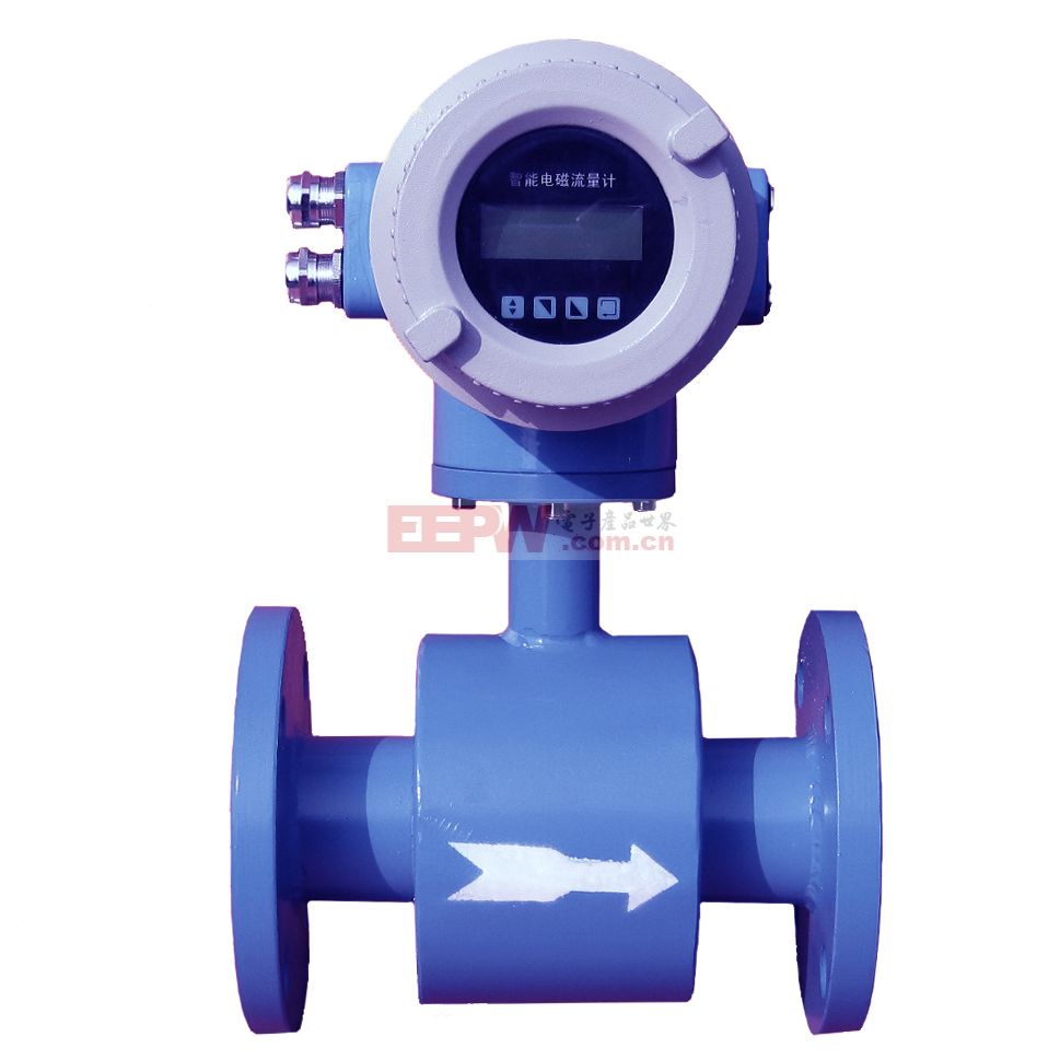
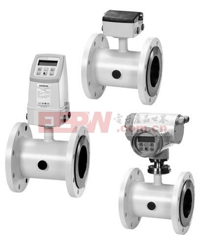
An electromagnetic flow meter, also known as EMF, consists of two main parts: a sensor and a converter. It is used to measure the volume flow of conductive fluids with a conductivity above 5μS/cm, such as acids, alkalis, salt solutions, mud, and pulp. Due to its reliability and accuracy, it is widely applied in industries like oil, chemical, paper, and water management.
Second, the Principle of Electromagnetic Flow Meter – Measurement Principle
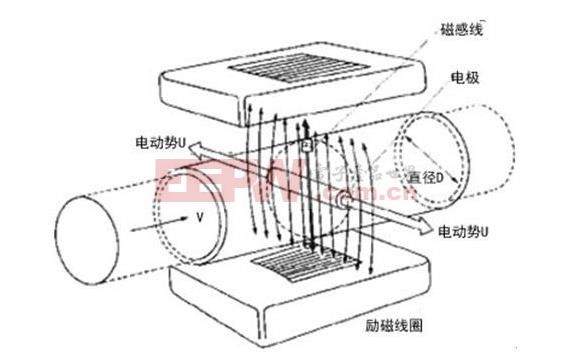
The basic principle behind an electromagnetic flow meter is Faraday’s law of electromagnetic induction. When a conductor moves through a magnetic field, an electromotive force (EMF) is induced at both ends. The magnitude of this EMF depends on the length of the conductor in the field, the speed of movement perpendicular to the field, and the direction can be determined using Fleming’s right-hand rule.
When a conductive fluid flows through a magnetic field, it cuts across the field lines, inducing an EMF between electrodes placed on either side of the pipe. The formula for this EMF is Ex = KBDV, where K is a constant, B is the magnetic field strength, D is the pipe diameter, and V is the average fluid velocity.
The volume flow rate Qv is calculated by multiplying the velocity V with the cross-sectional area of the pipe, πD²/4. Substituting Ex into the equation gives Qv = πD * Ex / 4KB. Thus, the flow rate is directly proportional to the induced EMF.
Third, the Principle of Electromagnetic Flow Meter – Working Principle
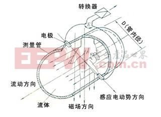
Based on the measurement principle, an electromagnetic flow meter uses an excitation coil to generate a uniform magnetic field around the pipe. Electrodes are installed on the pipe wall, perpendicular to the magnetic field, to detect the induced EMF. Once measured, the signal is sent to the converter, which amplifies, filters, and processes the data to display the instantaneous and total flow rates on the screen.
Fourth, the Principle of Electromagnetic Flow Meter – Working Conditions
The operation of an electromagnetic flow meter relies on certain assumptions, though they may not always hold perfectly in real-world applications, leading to minor inaccuracies. These assumptions include:
- The magnetic field produced by the coil is uniform and constant.
- The fluid flow is uniform.
- The fluid is non-magnetic.
- The fluid has uniform and isotropic conductivity.
The principle of the electromagnetic flow meter is quite fascinating. If you're eager to dive deeper, check out these related topics:
- 1. The working principle of electromagnetic flow meters – learn more
- 2. The basic principles of electromagnetic flow meters
- 3. Application of electromagnetic flow meters in the chlor-alkali industry
- 4. Factors affecting performance and installation considerations
- 5. A comparison of advantages and disadvantages of different flow meters
Electromagnetic Flowmeter
waterproof ac adapter,waterproof 12v dc power supply,water clarifier power adapter,Waterproof power supply
FOSHAN SHUNDE KELICHENG POWER SUPPLY TECHNOLOGY CO., LTD , https://www.kelicpower.com