Foreword
This article refers to the address: http://
Most of the portable electronic products use lithium-ion batteries or nickel-hydrogen batteries. However, the current energy density of lithium-ion batteries is approaching the theoretical limit. In comparison, fuel cells have great energy density development space, such as methanol and the same volume of lithium ions. Compared with the battery storage capacity, methanol has about 20 times of calorific value. If it has 20% power conversion efficiency, it can generate several times of electrical energy. In addition, the fuel cell does not require lengthy charging time, and it also recycles resources and reduces battery use. The volume has a positive contribution, so the development of micro fuel cells has received global attention.
The portable electronic products with micro fuel cell is divided into: passive and active direct methanol (the Methanol) of the fuel cell (DMFC: Direct Methanol Fuel Cell) and attached to the fuel reformer of the polymer electrolyte fuel cell (PEFC: Polymer Electrolyte Fuel Cell) two kinds of . This article describes the use of MEMS technology to make valves, reformers, injectors and other micro fuel cell components, as well as the development of micro fuel cells.
DMFC characteristics
system structure
The DMFC is divided into two types: passive and active. The active DMFC provides air and fuel cells. There are almost no dynamic components in the structure. The specific method firstly injects the methanol solution with the mixing ratio adjusted into the fuel tank, and then transfers the fuel to the capillary. battery, in this case, high energy density, is a common means of increasing the concentration of the aqueous methanol solution, however, a result of methanol from the anode through the polymer electrolyte membrane: when (PEM polymer electrolyte Membrane) to the cathode, bleeding "methanol Cross Over" The phenomenon is very serious, and this phenomenon is electrically equivalent to the internal short circuit of the fuel cell, so the output and efficiency will drop significantly.
The active DMFC uses a dynamic component such as a pump or a value to deliver air and fuel to the battery. Figure 1 shows the structure of the active DMFC system. The specific method firstly injects methanol with a concentration close to 100% into the fuel tank, dilutes it with water, and then delivers it to the battery. The methanol aqueous solution is circulated by the pump, and its concentration is controlled within a certain range (approximately About wt%), so that you can continue to obtain high energy density fuel, while also inhibiting the Methanol Cross Over phenomenon. In other words, the methanol aqueous solution uses the pump cycle to smoothly remove the carbon dioxide gas and raise the fuel, and then use the pump to force the air to be transported. At the cathode, the generated water is recycled and reused (Recycle).
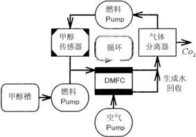
Figure 1 Active DMFC system structure
Micro fuel valve
The fuel supply system of 1W to several W grade micro fuel cells requires characteristics such as small size and low power consumption, such as compressed air or liquid steam with appropriate steam pressure, or pressurization of fuel by spring, fuel tank and closing the valve provided between the battery normal (Normal Cross Value), which may be provided with valve opening as the battery needs an appropriate amount of fuel to the battery, so the valve must have the following requirements:. a size of a semiconductor chip; B low power consumption; c. The valve can be closed corresponding to the pressurized liquid; d. High mass productivity.
Regarding the requirements for low-consumption power and mass production in items (b) and (d) above, the researchers reviewed the piezoelectric and electromagnetic methods. Basically, the piezoelectric method and the electromagnetic method must use components such as piezoelectric and magnet, and the manufacturing process is not suitable for the semiconductor; the heating method is relatively simple, and the displacement and the mechanics also meet the above requirements, but the heat energy of the liquid system is dissipated. It is not easy to achieve low-consumption power targets, so the researchers finally decided to use electrostatic means to drive the micro-valves.
The main problem of the electrostatic method is low driving voltage. Although the electrostatic actuator itself hardly consumes power, once the driving voltage is increased, the boosting circuit itself consumes power.
In addition to reducing the electrostatic gap, the method of lowering the driving voltage also needs to reduce the rigidity of the actuator, so that the low-rigidity actuator simultaneously meets the above items (b) and (d), and the item (c) can correspond to the pressurized liquid. The requirement to close the valve action.
Figure 2 is a cross-sectional view of a micro-fuel valve with a pressure-balanced structure. As shown in the figure, once the pressurized fuel is injected into the valve, the pressure of the fuel is used, and the force of opening the valve appears in the electrostatic actuator. If there is no special design, the actuator is When the rigidity is very low, the fuel will open arbitrarily once it flows into the valve.
As shown in Fig. 2, the valve is lifted by the pressure balance diaphragm (Balance Diaphragm) of the fuel, and the volume of the pressure balance chamber is reduced in a sealed state, so that the pressure rises the electrostatic actuator to push downward, and the positive and the back of the electrostatic actuator are received. The pressure difference is small, and the force of closing the valve appears in the electrostatic actuator. It can be seen that the micro fuel valve uses the pressure balance of the positive and the back of the electrostatic actuator to achieve the normal cross requirement. According to the test result, the pressure balance mechanism can effectively operate. The inlet pressure can be kept closed even if it is lower than 20 kPa, and the driving voltage of the valve is about 30 to 60V.
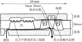
Figure 2 Micro-fuel valve with pressure balanced structure
PEFC characteristics with fuel reformer
The PEFC with the fuel reformer can reform the hydrogenation-based fuel to produce hydrogen, which is then sent to the battery for power generation. Micro-fuel cells for portable electronic products use methanol steam reforming of the following reaction formula:
Since the steam reforming reaction is an endothermic reaction, it is necessary to use a catalytic converter as a heat source. In addition, the carbon monoxide, a by-product of the steam reforming reaction, poisons the catalyst of the PEFC. In this case, carbon monoxide is removed, so the selection is made. The oxidation reactor is also a hydrogen separation membrane. Fig. 3 is an internal structure of a fuel reformer PEFC.
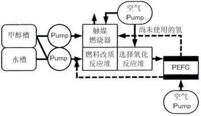
Figure 3 shows the internal structure of the fuel reformer PEFC
Although the fuel reformer PEFC system is more complicated, it has the following advantages:
• The output density of PEFC fueled by hydrogen is several times higher than that of DMFC or even more than one digit. If the fuel reformer is integrated, it is theoretically possible to achieve a higher output density than the DMFC system.
• The fuel reformer PEFC system can also generate electricity using hydrocarbon fuels other than methanol such as Butane or Athanol.
Research and development of fuel reformers, the United States Pacific Northwester National Institute (PNNL), LECUNT, Japan CASIO, Northeastern University and other units are most active, such as Japan's CASIO company using glass substrates to develop a size of about 20 × 20mm methanol modified micro-reactor (Reactor), selective oxidation reactor and catalytic converter, and then combine these components into a fuel reformer with a power generation of 2.5W.
Figure 4 is a fuel reformer structure in which a fuel reforming reactor, a catalytic converter, and a heat insulating structure are integrated by using MEMS. Basically, it is a self-supporting film made of MEMS technology, and the reforming reaction and the catalytic combustion are performed. In the case of methanol steam reforming, it can heat the reaction unit to the surrounding temperature to obtain a temperature of 200~300 °C, thus greatly reducing its heat capacity. For example, when the channel width of 300 μm and 7 mm is heated to 300 ° C, it can be reduced by 0.64 W. When the power is supplied to the left and right, and one flow path is heated to 300 ° C by a Micro Heater, the temperature of the substrate around the flow path is only about room temperature.
The methanol steam reforming of the above-mentioned micro fuel reformer can be used as a self-supporting catalyst combustion, but is limited by the performance of the catalyst, so the amount of hydrogen generated is equivalent to 200 mW, and the thermal efficiency is only about 6%.
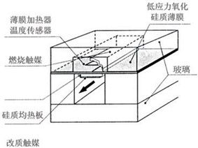
Figure 4 Fuel reformer with self-supporting membrane structure
The main feature of the micro fuel reformer of Figure 5 is that a methanol steam reforming reactor and a fuel evaporator are arranged on both sides of the catalytic converter. The overall size of the reformer is 25×20×5.6 mm, and the methanol is supplied at a speed of 2.4 ml/min. An aqueous solution (water vapor/methanol ratio S/C = 1.9) can produce hydrogen equivalent to 4.7W.
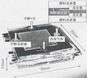
Figure 5 Micro-integrated micro-fuel reformer
The micro-fuel reformer must have a heat source, that is, a burner. In addition to this, a component that can transport a mixture of fuel and air to the burner is required. Therefore, the researchers use the liquid gas vapor pressure to develop a mixture that can effectively mix the gas. Micro Ejector delivered to the burner.
In the case of butane, in order to completely burn Butane, it is necessary to provide 31 times the volume of butane. If a large amount of air is transported by a general micropump, the volume and power consumption of the micropump are very considerable and impractical.
The injector utilizes the negative pressure generated by the inertia of the primary fluid jet to attract the secondary fluid with the viscous pull effect. Figure 6 shows the internal structure of a micro-injector made by MEMS technology. When the flow rate of isobutane is equivalent to 20W, the micro-injector can inhale 35 times of air, but the air intake is drastically reduced as the outlet pressure increases. Therefore, the pressure loss of the burner must be very low.
The inner micro-miniature fuel reformer burner, when only a few Pa 10W combustion pressure loss, micro-switch is necessary if the injector significantly reduce the pressure loss, the researchers are using CFD (Computational Fluid Dynamics) attempted to develop higher performance Structure.
The micro-injector uses Exergie with liquefied gas vapor pressure to attract air, which means that the micro-injector must integrate a low pressure loss high-pressure micro-valve. Figure 7 shows the structure and operation principle of the micro-injector micro-valve. The micro-valve uses static control to control the large-fluid drive valve. The main features are as follows:
·Open state low pressure loss
·High Leak withstand pressure Normal Cross action
·Low consumption power
The pressure source of the fluid-driven valve is also controlled by liquid gas, so no external pressure is required. The microvalve of Fig. 7(a) is closed, and the electrostatic drive valve is open on the left side. When the electrostatic drive valve on the right side is closed, the liquid gas is transferred to the central fluid drive valve connected to the micro injector. The central fluid-driven valve is pressed against the diaphragm to form a closed shape. It is worth mentioning that both electrostatically actuated valves are disposed at a position where liquid gas is applied and the valve diameter is only 20 μm (the driving voltage is 30V), which means that MEMS technology is very suitable for making fluid-driven valves.
The microvalve of Fig. 7(b) is open, and the electrostatic drive valve is closed on the left side. Once the right electrostatic drive valve is opened, the lower side of the central fluid drive valve connected to the microinjector opens the atmosphere, and then uses air. The central fluid actuated valve is squeezed downward to become open.
Since the diaphragm supporting the valve is processed into a corrugation that can be largely displaced, the desired target of "low pressure loss in the open state" can be achieved, and the pressure loss is only 1.7 kPa at 10 cc/min. The deliberate Leak was not detected even when the pressure difference was 160 kPa.
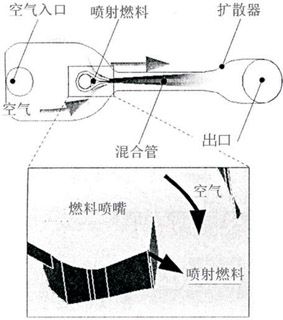
Figure 6 Micro-injector internal structure
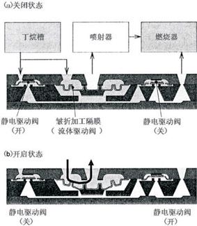
Figure 7 Micro-injector internal micro-valve structure
Development trend of micro fuel cells
At the beginning of 2000, foreign research institutes such as the United States and Japan continued to use MEMS technology to develop micro fuel cells. Among them, the silica separator (Silicon Separator) micro fuel cell (Fig. 8) published by Kelly was the simplest structure, and other research units also launched. the same type of fuel cell, cell i.e. the heart of these cells 'anode catalyst', 'ion conductive film', 'cathode catalyst', are the use of traditional PEFC membrane electrode assembly (MEA: membrane electrode Assembly)?, is called MEA The catalyst film was attached to both sides of the PEM using a hot press (Hot Press) technique.
The traditional PEFC locks the MEA with a separator, and the structure must be combined with a plurality of components. Therefore, it is not suitable for fabrication by MEMS technology. Therefore, Morse's anode, PEM, and cathode film are sequentially formed on the silicon substrate to form the structure of FIG. 8(b). The micro fuel cell is shown, the anode and cathode films are made by sputtering, and the PEM film is made by spin coating, so that a monolithic structure can be obtained. The micro fuel cell uses hydrogen as a fuel, 90 ° C. An output density of 3.8 mW/cm 2 can be achieved.
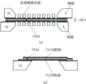
Figure 8 Micro-burning battery internal structure
Since the single cell voltage of a fuel cell is usually only about 0.4 to 0.8 V, a plurality of Cell series connections are commonly used to increase the voltage. There are four main battery connection methods as shown in Fig. 9. Fig. 9(a) shows the connection method used in general fuel cells. This connection method is also called "Bipolar Stocking".
The connection method of FIGS. 9(b) to (d) is to form a fine structure on the substrate, and it is generally considered that this method is suitable for fabrication using MEMS processing.
Figure 9 (c) A fuel cell composed of a plurality of Cell connected in series, although this method must transfer fuel to both sides of the battery, but no wire connection is required from one end of the battery to the opposite side of the substrate, if and FIG. 9 (b) Compared with the connection method, it is relatively easy to assemble and wire, so Lee's micro fuel cell also uses this type of connection called "Flip Flop Interconnection".
Fig. 9(d) shows another connection method in which a plurality of cells are connected in series, and since the adhesion to the PEM catalyst electrode during the test is insufficient, only an output density of 1 μW/cm2 can be obtained, but Mayers and Maynard. According to the calculation results, the volumetric output density of the cathode and anode is obtained. According to the calculation results, the volumetric output density of about 40% can be obtained. Motokawa can test the micro DMFC according to the above structure and obtain 0.78 when using the aqueous solution of sulfuric acid added with sulfuric acid. Output density of mW/cm2.
In addition, researchers used sputtering technology to make catalyst electrodes on the Porous Silicon surface. D·Arrigo and Hayase replaced electrolytic sputtering with sputtering to try to obtain higher performance catalyst electrodes.
Screen printing technique using a catalyst made of platinum electrodes patterned Pichonat Carbon Paste apos proton (Proton) conductive resin? (Nafion, Du-PONT) soaked in Porous Silicon, and then it is made as a micro-fuel cell PEM Gold's Porous Silicon is immersed in sulfuric acid to make PEM. The main purpose of a series of cumbersome processing is that PEM is not easily swelled by water or methanol to prevent PEM from peeling off.
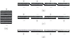
Figure 9 Cell serial connection
Conclusion
The above describes the use of MEMS technology to make valves, reformers, injectors and other micro fuel cell components, as well as the development of micro fuel cells.
At present, most portable electronic products use lithium-ion batteries or nickel-hydrogen batteries. However, the energy density limit of traditional rechargeable batteries and the annoying charging time have greatly limited the degree of freedom of use, so the development of micro-fuel cells has been highly valued worldwide. Among them, Japanese manufacturers are the most active. In fact, some mobile phones have already started to use micro fuel cells. It is generally believed that with the advent of next-generation mobile phones, the future of micro-fuel cells will become the main source of power for portable electronic products.
Metal Pole, Metal Light Pole, Metal Power Pole, Metal Utility Pole
YIXING FUTAO METAL STRUCTUAL UNIT CO.,LTD( YIXING HONGSHENGYUAN ELECTRIC POWER FACILITIES CO.,LTD.) , http://www.chinasteelpole.com