Abstract: In the circuit design to achieve weak signal amplification, high-speed signal acquisition, high-power output and other functions, must use analog circuits, but for a long time the design of analog circuits has been the drawback of low processing accuracy, design and debugging difficulties. Based on this, the gain design of the amplifier was carried out using the system programmable analog circuit referred to as ispPAC introduced by LatTIce. It allows designers to use EDA software to design and modify analog circuits on a computer, and to simulate them. Finally, the design can be downloaded to the chip through a programming cable. By developing software, you can adjust the performance of the circuit such as gain, bandwidth and threshold. Here are several techniques for implementing gain adjustment of analog signals using ispPAC10.
Keywords: gain; programmable analog device; ispPAC10
1 structure and principle of ispPAC10
1.1 Structural features of ispPAC10
The structure of the ispPAC10 device consists of four identical signal processing blocks (PAC blocks), analog wiring pool, configuration memory, reference voltage, auto-correction unit and ISP interface, as shown in Figure 1.
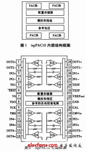
The ispPAC10 pin is shown in Figure 2.
Its package form is:
28-pin DIP or SOIC package.
The pin functions are as follows:
Input: 3,4,11,12,17,18,25,26
Output: 1, 2, 13, 14, 15, 16, 27, 28
Digital L/O: 5, 6, 8, 9, 10, 20
Power supply pin: 7, 21
CMVIN pin: 19
Test pin: 23, 24
(The supply voltage is 5 V; the power supply pin is bypassed to ground with a 10μF tantalum capacitor and a 1μF ceramic capacitor for optimum performance).
1.2 How is ispPAC10?
The ispPAC10 device has four identical base unit circuits. Each PACblock contains two independently programmable input amplifiers, a differential output amplifier, a resistive feedback component (openable), and an adjustable feedback capacitor. The input of the PACblock is two pairs of differential inputs, and the gain can be adjusted in integer steps from ±1 to ±10. The feedback loop of the output summing amplifier consists of a resistor and a capacitor in parallel.
The input impedance of each PACblock is 109 Ω. The input amplifier can be modeled as a programmable gain block (K1 and K2) and a summing resistor. The current supplied by the input amplifier is accumulated at the inverting input of an operational amplifier. The feedback amplifier's feedback network can be modeled as a fixed-value resistor with an adjustable capacitor in parallel (the adjustable capacitor value is 120 values ​​between 1pF and 62pF). The resistive feedback path can be disabled. The output of the op amp is a differential voltage.
Electronic Burglary Safes
Electronic burglary Safes are safes that have passed Chinese 3C certification and use digital password lock systems.
Details:
They are convenient, safe and easy to use;
The safes provide high levels of security;
The Passwords can be changed easily to prevent theft and they`re also quite convenient for official usage because the personnel turnover in the office is normal, hence changing passwords is necessary;
3 times wrong passwords will cause alarm;
The emergency supply can be used when the electricity is off or in case of a black out or EMP Surge;
They possess elegant designs hence they not only provide protection but also serve as decoration pieces.
Electronic Mini Safe,Electronic Safe Box,Electronic Security Safe,Electronic Lock
YONGFA INTELLIGENT TECHNOLOGY SECURITY CO., LTD. , http://www.yongfa-safe.com