Reducing carbon dioxide emissions is the hottest topic in today's automotive sector. The European Commission recently announced a road map for safer and greener cars by 2012. Significant changes in the way consumers buy cars also confirm that consumers want cars that have the highest fuel efficiency to meet their personal and professional needs. With advances in blended fuel technology, automakers are introducing new cars that reduce carbon dioxide emissions. There are also technologies that are also working on this goal, such as Blue Motion, Econetic and Efficient Dynamics.
This article refers to the address: http://
It is also a fact that the pollution rate of diesel engines is higher than that of gasoline-powered vehicles. In particular, diesel particulates can cause damage to the human body, causing lung discomfort, cancer and heart disease. Older diesel engines emit large visible particles, like black smoke, and the new engine emits particles that are generally small and cannot be seen with the naked eye.
To make these emissions cleaner, automakers have built diesel particulate filters (DPFs). These filters have been used in off-road vehicles since 1980 and have been used in some general cars since 1996. DPF now captures diesel soot particles down to 2.5 microns, thus reducing particulate emissions from 60% to 7%. DPF uses a porous ceramic material that eventually saturates and needs to be cleaned and regenerated. For this type of maintenance, the DPF needs to be heated to an exhaust temperature of +600 °C or higher. In order to achieve this higher than normal temperature, the ECU (Electronic Control Unit) temporarily delays the injection and limits the inhalation. At this point the sensor becomes a critical control element: by measuring the pressure drop across the filter with a pressure sensor, the most efficient point at which the regeneration process begins can be determined.
Interface implementation
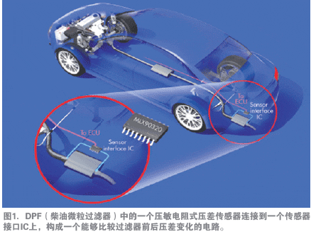
Taking the diesel filter module as an example, we installed a differential pressure sensor using a conventional varistor component in the DPF. This sensor checks a small pressure range, typically 0 to 15 psi. A sensor interface IC (such as Melexis' MLC90320 CMOS analog sensor interface) is connected to the output of the sensor to form a resistive Wheatstone bridge circuit. This interface converts the small change voltage of the resistor (usually a few millivolts) into a fairly large output voltage variation. With this configuration, the circuit can compare the pressure signals before and after the filter (Figure 1). The interface chip amplifies and corrects the signal of the sensor and converts it into a value that the ECU can recognize. When the DPF is saturated, the interface detects a large pressure difference between the signals before and after the filter. The interface IC amplifies and compensates for this difference and passes it to the ECU. This process allows the sensor interface to control the communication between the sensing element and the ECU to ensure continuous operation of the filter.

Sensor interface
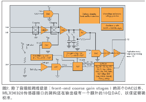
In the above example, the varistor sensing element is coupled to the input of the sensor interface, which compensates for the gain and offset of the signal to determine that there is a well calibrated output signal. In addition, 3-bit and 10-bit digital-to-analog converters (DACs) are used in different coarse-tuning stages. The output interface of this special interface uses another 10-bit DAC to accurately calibrate the output variation range (Figure 2). ).

The device's architecture makes it easy to detect a few millivolts of sensor output and achieve a 4V accurate output range. To ensure smooth compensation adjustment of the interface chip, we have added a coarse compensation correction to compensate for large offset changes in the sensing element and use an adjustable 10-bit compensation. The sensor interface can also be connected to an internal or external temperature sensor when considering temperature issues.
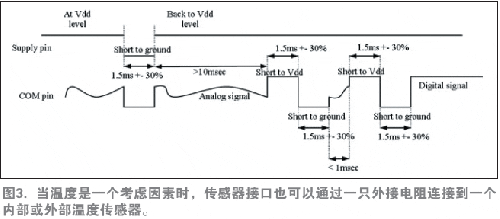
However, if the temperature around the sensor in the application is different from the temperature around the interface, it is best to use only one external temperature sensor. By connecting an external resistor to the temperature chain used to adjust the bias and gain, the interface can perform accurate 10-bit temperature measurements when necessary (Figure 3). This allows the external temperature sensor to be mounted as close as possible to the pressure sensor.

Programmable clamp
Another unique feature of the sensor interface is its ability to implement programmable clamping at low output levels and high output levels. Clamping ensures the ability of the sensor to detect the lowest and highest output levels, and the ECU can check if the sensor's output is within an acceptable range. In addition, the sensor interface in our example also integrates fault detection and is therefore suitable for a range of automotive applications. When it detects an internal or external fault, the device can detect a bad connection of the sensing element.
If the chip receives an incorrect input level from the sensor, such as below 1.5V or above 3.5V, there may be a short to ground or power supply and the IC will generate an output level that is outside the clamp level range. The ECU thus detects the event. This dedicated interface IC is capable of programming the sensor interface through the actual connector. The module containing the sensing element and interface is housed in a housing with only the application pins connected to the outside of the module. It is not necessary to add other communication lines because the output pins can be used as analog output pins or as communication pins. With short-circuit detection, the IC knows that the user is requesting a pin for communication. To ensure that memory parameters do not change during a short circuit, this test is based on a specific timing action. In addition, the interface chip contains an option to lock the EEPROM to avoid accidentally changing the calibrated device. In fact, by using the output of the interface, we can communicate with the chip and correct the parameters in the EEPROM with user-defined features.
An evaluation board is available for the calibration interface. These boards include all the hardware, companion software, and production software required to communicate with the interface. Production software controls all necessary production equipment and communicates with the equipment to quickly calibrate hundreds of samples.
Conclusion
Sensor interfaces are ubiquitous in cars. They convert sensor signals into a readable format and filter out interfering external components to ensure accurate information is sent. We find all types of sensors in common rail, suspension and shifting systems, as well as HVAC applications, fuel injection systems, engine controls, brake anti-lock systems, and many other places in the car. They are so widely used that people can almost forget them. Understanding their performance can facilitate the use of these irreplaceable products in more and more applications.

Led Grow Par Light,High Par Led Grow Light,Full Spectrum Led Grow Par Light
Shenzhen Mingxue Optoelectronics CO.,Ltd , https://www.mingxueled.com