Electric shock protection is an important part of the electrical safety design of power battery system. Generally speaking, it can be realized through two types of ways: First, direct contact protection, such as insulation design, screen protection (blocking/enclosure, IPXXB/IPXXD, etc.); It is indirect protection, including equipotential bonding, electrical isolation (interval, creepage distance). Here is some understanding and understanding of equipotential potential.
What is an equipotential bonding?
In electrotechnical terms, equipotential bonding, also called protective grounding, is defined in the book "Lightning and Lightning Protection Engineering" as follows: "Equipotential bonding is the removal of all metal objects in and around a building, such as steel in concrete. , water pipes, gas pipes and other metal pipes, machine base metal objects and other large buried metal objects, cable metal shields, neutral lines of power systems, and grounding lines of buildings are connected by electrical connection method (welding) Or a reliable conductive connection) makes the metal inside the building a good equipotential body."
In the national standard GB/T18384-3:2015 "Electrical Vehicle Safety Requirements Part 3", the equipotential bonding (potential equalization) is defined as: the potential difference between the exposed conductive parts of the electrical equipment is minimized.
Why do you need equipotential bonding?
In the process of continuous development and renewal of electrical safety technology, it has been noticed that a large number of electrical accidents are caused by excessive potential differences, such as lightning accidents, because the tens of thousands of volts generated by lightning are directly applied to the human body and Between the earth, the huge potential difference produces a large instantaneous current, causing people who are struck by lightning to suffer casualties due to respiratory pauses or paralysis of the heart. Compared with lightning strikes, more people around the world have suffered casualties due to electric shocks from civilian electricity or industrial electricity. The principle is the same as that of lightning strikes, which is caused by the large potential difference between charged parts in different parts of the human body. Serious injury.
Internationally, it attaches great importance to the role of equipotential bonding, which is necessary for the safe operation of electric power, lightning protection and the normal operation and safe use of electronic information equipment. After the equipotential bonding, the fault voltage in the system power line can be prevented from causing electric shock accidents, and the potential difference, arc, spark spark probability can be reduced, and electrical fire accidents and personal electric shock accidents caused by ground faults can be avoided.
The role of equipotential bonding is mainly as follows:
Preventing personal electric shock: Make a good metal connection between the un-charged metal conductor part of the electrical equipment and the grounding pole during normal operation to protect the human body and prevent electric shock.
Ensure the normal operation of the electrical system: the grounding of the power system is generally neutral grounding, the grounding resistance of the neutral point is very small, so the potential difference between the neutral point and the ground is close to zero.
Protection against lightning and static electricity: Static electricity and electromagnetic induction will occur during lightning strikes. Static electricity caused by friction during production and transportation may cause electric shock or fire.
In electric vehicle products, if the maximum voltage of the entire battery pack exceeds 60V (DC), it has exceeded the range of human body safety voltage, and equipotential bonding must be performed to ensure safe use.
In the case of equipotential bonding, even if the insulation of the positive or negative pole of the battery pack fails with the battery pack housing, since all bare metal parts on the vehicle have reached the same potential through equipotential bonding, the human body contacts these When metal parts are used, no current is generated, and the human body is still safe on the vehicle, and there is no electric shock.
What are the equipotential bonding standards related to electric vehicles?
1GB/T 18384-3 electric vehicle safety requirements - Part 3:
2EN 1987-3 Electrically propelled road vehicles-Specific requirements for safety-Part3: ProtecTIon of users against electrical hazards
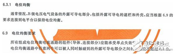
3ISO 6469-3 Electrically propelled road vehicles-Safety specificaTIon-Part3: ProtecTIon of persons against electric shock GB/T 18384-3 The design requirements and test requirements for equipotential bonding are specified in standards 6.3.1 and 6.9.
Some customers have established equipotential bonding requirements that are more stringent than those of GB/T18384-3:2015 and ISO6469-3, requiring impedances of equipotential bonding to be less than 0.01 ohms.
So, for the power battery system, how to design the equipotential bonding?
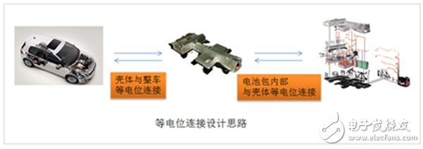
Design ideas:
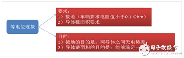
Design principle:
Design:
First, the housing of the battery box must be equipotentially connected to the ground of the vehicle (vehicle housing), either by ground connection or by thick bolt connection, depending on the overall design of the vehicle.
Key points:
1) Ground wire connection, the ground wire color is black;
2) Thick bolt connection
Secondly, all accessible conductive metal parts (such as cover plates, brackets, water-cooled tubes, etc.) on the battery case must be equipotentially connected to the housing, which can be soldered, crimped, bolted, etc. Ways to achieve. If the equipotential bonding is achieved by crimping or bolting, the contact surface cannot be painted or insulated, otherwise the contact impedance is too large to meet the requirements. For bolts with equipotential bonding, the type and torque, etc. also have corresponding specifications.
Key points:
1) Welding, welding reliability;
2) Crimp, the contact surface can not be painted or insulated, otherwise the contact impedance is large and cannot meet the requirements;
3) Bolt connection, the contact surface can not be painted or insulated, otherwise the contact impedance is large and can not meet the requirements;
Type and torque have corresponding specifications.
Again, the conductors used for equipotential bonding (such as grounding wires, etc.) are required to be black in color for easy identification during maintenance and disassembly. The cross-sectional area of ​​the conductor for the equipotential bonding and the area of ​​the contact surface must be not lower than the cross-sectional area of ​​the high-voltage harness. This is mainly due to the possibility of high-voltage current flowing through the equipotential circuit when insulation failure occurs, if the equipotential bonding is cut The area is not large enough, and it is likely to be hot due to overcurrent, which in turn causes a fire.
Key points:
1) The cross-sectional area of ​​the conductor and the contact surface area for equipotential bonding must be guaranteed not lower than the cross-sectional area of ​​the high-voltage harness
2) The connection points need special treatment to avoid the corrosion caused by the potential difference between different materials.
Of course, in product design, the technical realization of equipotential bonding is not limited to the technical requirements of customers. According to the specific conditions of the product, sufficient measures and means should be taken to ensure the requirements of potential connection, thus ensuring the safe use of the product. .
Here are two points to emphasize:
(1) Some colleagues are confused about equipotential and grounding. Here are the following:
Commonality: the requirement must be that the connection resistance is small enough so that there is no potential difference between the connected two conductors, and the color of the surface of the line body is also required (the color requirements of different fields are different);
The difference is that the grounding does not strictly require the current carrying capacity of the grounding wire, and the equipotential has a clear current carrying requirement for the connecting wire: greater than but not lower than the cross-sectional area of ​​the main power harness, that is, the current carrying capacity is equal to or greater than the main power harness.
(2) Some electric bus batteries are connected to the chassis with insulating mats, which is risky. Typically, the BMS's insulation monitoring subsystem is connected at one end to a high voltage (high voltage positive or high voltage negative) and at the other end to a 24V ground (ie, the chassis). The BMS determines whether the insulation has failed by collecting the potential difference between the high voltage positive/negative and the chassis. When the electrical box enters the water and the insulation resistance between the electrical box and the high voltage fails,
Since the insulation box is used between the electric box and the body, the box is not connected to the BMS, so the BMS can only detect the insulation failure of the high voltage and the body, and cannot detect the insulation failure of the box and the high voltage.
How to design and test the equipotential bonding?
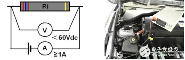
For the verification of equipotential bonding, the test method given in GB/T18384-3:2015 is in the standard 7.4 part:
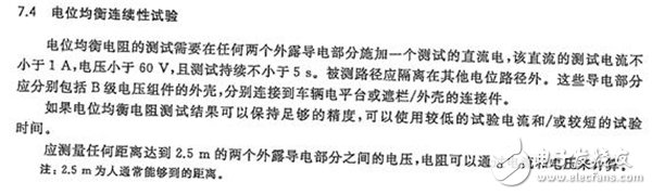
The test diagram and examples of GB/T18384-3:2015 are shown in the following figure:
Absolute rotary Encoder measure actual position by generating unique digital codes or bits (instead of pulses) that represent the encoder`s actual position. Single turn absolute encoders output codes that are repeated every full revolution and do not output data to indicate how many revolutions have been made. Multi-turn absolute encoders output a unique code for each shaft position through every rotation, up to 4096 revolutions. Unlike incremental encoders, absolute encoders will retain correct position even if power fails without homing at startup.
Absolute Encoder,Through Hollow Encoder,Absolute Encoder 13 Bit,14 Bit Optical Rotary Encoder
Jilin Lander Intelligent Technology Co., Ltd , https://www.jilinlandertech.com