1 The basic structure of the dimmer
The dimmer is a typical closed-loop control system with 80196 single-chip microcomputer as the core. The system uses the method of controlling the current of the strong electric circuit to realize the control of the brightness of the lamp. The system adopts a modular structure. Among them, the 80196 MCU is the core module of the system. It combines the digital regulator with the system control and scheduling functions. The system uses the high-speed input/output of the 80196 MCU as the phase synchronization and controllable of the thyristor. The trigger signal of silicon uses the 80196 10-bit A/D converter as the current/voltage input interface of the system. The system is equipped with a digital current controller, which constitutes a current closed-loop system. In addition, the system also has current and voltage detection module, thyristor trigger pulse isolation amplification module, phase synchronization and contactor control module, display and key control module, etc. The basic structure is shown in Figure 1.
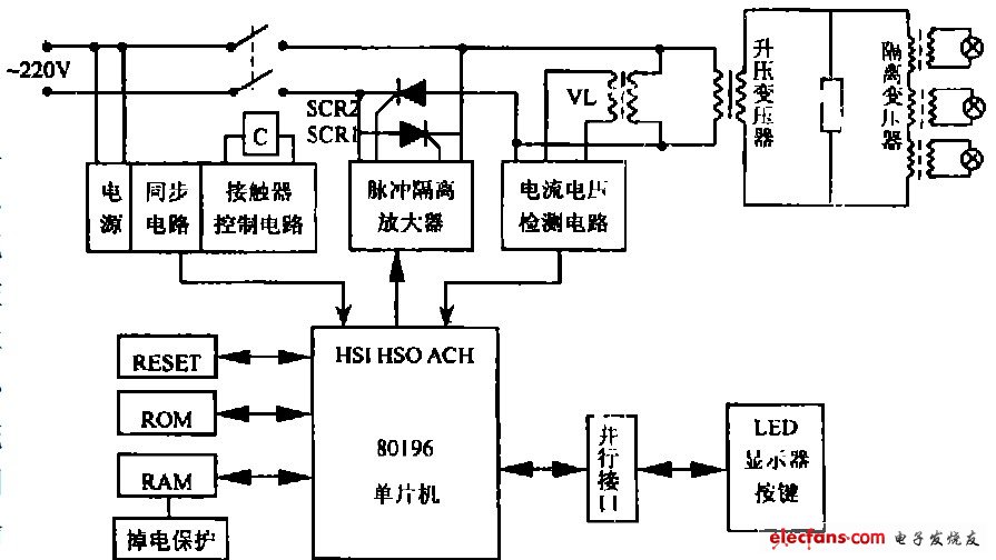
Figure 1 The basic structure of the dimmer
2 Current balance detection principle and circuit improvement
Since the navigation lights are installed along the runway, the transmission line from the transformer room to the end of the airport is 2~4 km, and the method of boosting power supply and step-down power supply must be adopted. The inherent characteristics of transformer operation require that the positive and negative trigger pulses of the thyristor circuit must be strictly symmetrical. Otherwise, the positive and negative half cycle current imbalance of the transformer is easily caused, and the equivalent DC is passed through the transformer, resulting in saturation of the magnetic circuit and the excitation reactance tends to zero. The powerful current is equivalent to the short circuit of the power supply. If it is not repaired in time, the fuse will be blown, the thyristor and the transformer will be burned out, causing a large-scale long-term blackout accident, which seriously threatens the increasingly busy flight transportation safety. Therefore, there is an urgent need for a kind of power supply. Online detection of transformer positive and negative current balancing technology. In addition, since the control site is in the vicinity of the high-voltage and high-current power grid, there is strong electromagnetic interference, and multiple high-power dimmers in the same site are put into operation or shutdown. Various relays and contactors often have clutch switches, and inrush currents are formed in the power supply. Intrusion into the control system from various ways, causing distortion of the detection signal, causing malfunctions, the program "runs away", in order to ensure the continuous and safe operation of the system, it must be considered to suppress various interferences in the hardware design to complete certain functions.
2. 1 Noise interference coupling analysis
There are several ways to interfere with coupling.
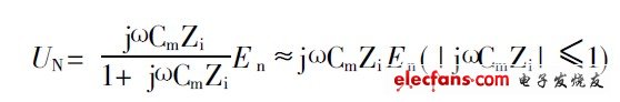
1) Electrostatic coupling: Noise is coupled into the circuit via stray capacitance, as shown in Figure 2-a. En is the source of interference, Cm is the parasitic capacitance, and Zi is the interference input impedance.
2) Electromagnetic coupling: The interference is coupled into the circuit via mutual inductance, as shown in Figure 2-b. In is the interference current, and M is the mutual inductance of the two circuits.
3) Common impedance coupling: The interference current is coupled into the circuit through a common impedance between two or more circuits. The common common ground connection is shown in Figure 2-c.
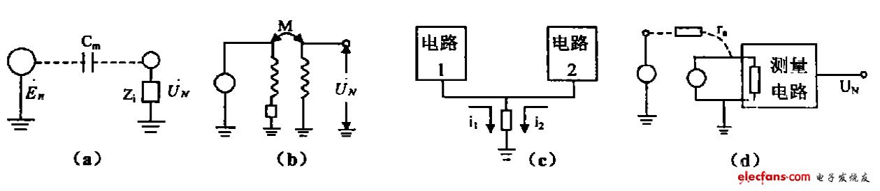
Figure 2 Several ways of interference coupling
4) Leakage current coupling: Due to poor insulation interference, the insulation current is coupled into the circuit as shown in Figure 2-d.

Among the above four types of interference, electrostatic coupling and electromagnetic coupling are proportional to the interference noise frequency. The higher the high-frequency noise content in the power grid, the greater the coupling interference, and their common feature is that they can be coupled together. Noise and interference are intruded from power, space, and process channels. The most difficult problem we face is process channel interference.
2. 2 The circuit of the original current balance detection method and its shortcomings
As shown in Figure 3, in order to make full use of the A/D conversion function of the 80196, the original detection circuit is designed to collect the current signal into a small signal voltage through the transformer, and use the diode to intercept the positive (or negative) half cycle, and then the amplification is effective. After the value converter AD536 is converted, the output resistance is amplified and adjusted, and the 80196A/D is collected for positive and negative weekly current comparison.
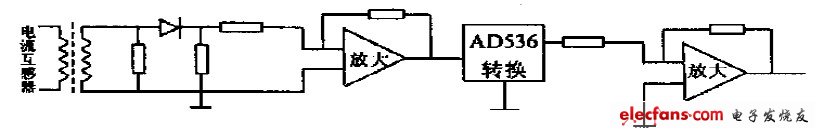
Figure 3 original balance detection circuit
Since the 80196 digital ground is connected to a peripheral circuit analog ground, and peripherals are likely to receive interference, the noise may enter the host along the A/D circuit, and the host may directly couple the noise, often "dead" due to interference.
Stereo headphone is important components of audio equipment. It has a wide frequency response, low distortion, power saving, strong audio resolution, clear surround sound, and good music rhythm. Stereo headphone is divided into earphone and headphone, which has the difference of left and right channels. It cannot be used interchangeably. Otherwise, the fidelity of the sound source and the resolution of the source frequency will be directly affected.

Stereo Headphones,Wireless Stereo Headphones,Bluetooth Stereo Headphones,Wireless Bluetooth Stereo Headphones
Shenzhen Linx Technology Co., Ltd. , https://www.linxheadphone.com