Abstract: Aiming at the requirements of high resolution graphic image video recording and remote monitoring, a technical solution based on FH8735 video and audio encoder is proposed. The scheme has the characteristics of simple structure, high compression ratio, stability and reliability, and can meet the application needs of various fields such as military and civilian.
Key words: FH8735; graphic image; compression; recording
0 Introduction In the application systems of security monitoring, civil aviation management and maritime affairs, high-resolution graphic image integrated video needs to be collected, compressed and recorded so that the actual scene and operation of the process can be reproduced after possible accidents and problems. Achieve analysis and tracing of responsibilities and causes. However, to complete the acquisition and compression of high-resolution graphics and video, it is necessary to solve the problem of the huge amount of video data and the efficiency, reliability and adaptability of the compression platform. This paper proposes a high-resolution graphics image compression scheme based on FH8735 video and audio encoder, which can complete video capture and compression, and send the compressed video data to the host storage through the PCI bus, or output through the Ethernet interface. Realize remote real-time monitoring.
1 Overall design The high-resolution graphics and image compression scheme based on FH8735 video and audio encoder consists of acquisition circuit, clock circuit, FH8735 compression circuit, network interface and power supply circuit. The overall block diagram of the program is shown in Figure 1.
This article refers to the address: http://
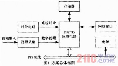
The circuit of each part in Figure 1 is introduced as follows:
(1) Video capture circuit. Completing high-resolution video acquisition by input matching and video acquisition circuits;
(2) Clock circuit. Consisting of a high-performance crystal oscillator, it provides a stable clock for the video acquisition circuit and the FH8735.
(3) FH8735 compression circuit. It consists of FH8735 audio and video encoder and DDR memory, completes video compression processing, and provides PCI interface and network interface control.
(4) Network interface. An external PHY chip that provides an Ethernet interface;
(5) Power circuit. Provide the required power for each functional circuit.
2 main design
2.1 Video Acquisition Circuit The video acquisition circuit is composed of TI's video image decoder TVP7002. The TVP7002 is a high-performance video image decoder with the following main functions and performance features:
(1) DC accuracy: 8/10 bits;
(2) Analog gain range: -6 ~ 6dB;
(3) Input component video signal resolution: 480i/576i~1080p;
(4) Input graphics signal resolution: VGA ~ UXGA;
(5) Digital video output format: YCbCr 4:2:2 and RGB/YCbCr 4:4:4;
(6) I2C bus interface.
The video acquisition circuit design with video image decoder TVP7002 as the core is shown in Figure 2:
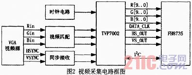
After VGA video input, the signal can be matched and filtered to access the TVP7002 decoder. The operating state of the TVP7002 decoder is set by the FH8735 video and audio encoder through the I2C bus according to signal characteristics and processing requirements.
2.2 FH8735 Video Compression FH8735 is a high-performance audio and video coding chip developed by FX Microelectronics. Its main technical features are as follows:
(1) Coding standard: ITU-T rrcommendation H. 264 ISO/IEC 14496-10 advanced video coding standard (MPEG4 Part 10), support H. 264 Main Profile and Baseline Profile;
(2) Support maximum resolution: 2048 × 1024;
(3) Support 1 channel 1080i HD/2 channel 720pi HD/8 channel D1 input;
(4) 8-channel I2S input interface; configurable as master mode and slave mode;
(5) PCI interface, 32bit, clock frequency 33/66MHz;
(6) 2 independent DDR SDRAM controllers, each controller has a word width of 32 bits;
(7) One MII/RMII interface supports 100/10Mbps speeds and is fully compatible with the IEEE802.3 specification;
(8) One channel video output interface, in line with BT.656 video standard;
(9) 2 independent I2C interfaces;
(10) JTAG download debugging interface;
(11) 16 bidirectional GPIOs.
FH8735 supports H. 264 Main profile and Baseline profile video compression format, can carry out 8 road signs clear 480i/576i real-time encoding, and can also encode one channel 1080i, two 720p high-definition signals in real time. In addition to high-performance video encoding capabilities, the FH8735 provides a rich video pre-processing feature for deinterlace, de-noise, OSD overlay, zoom, motion detection and other processing of input video. In order to configure an external video and audio receiver chip, the FH8735 provides two completely independent standard I2C interfaces to cope with possible external device I2C address conflicts. As a code coprocessor, the FH8735 is equipped with a flexible host interface. The host can communicate with the FH8735 via the PCI or HPI interface for control and status information, or access the FH8735 external DDR SDRAM. The FH8735 has two independent DDR controllers inside, which can be configured with one or two sets of external DDR SDRAM depending on the actual system requirements for encoder performance.
In order to meet the needs of some applications for preview video, FH8735 has a standard set of BT. The 656 video output port can divide and merge the multi-channel preview video outputted by the video pre-processing unit as needed, and encode the video output into a BT.656 format.
The video compression coding circuit with FH8735 as the core is shown in Figure 3.
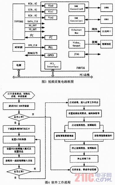
The FH8735 encoding chip receives the RGB data output by the TVP7002, and completes the video compression processing according to the working state set by the host. The compressed video data can be output through the Ethernet port, or can be locally stored through the PCI bus to the host.
2.3 Software Design FH8735 code chip software development manual provides system functions, video input, video preview, video coding, OSD function, video function, area mask, audio function, data acquisition nine kinds of functions, general work of engineering or test software The process is shown in Figure 4.
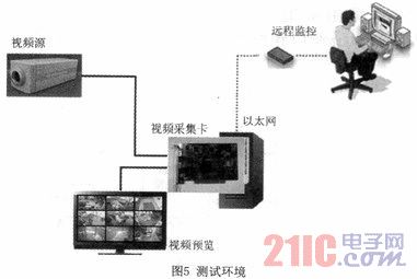
3 Test To verify the correctness and main functions and performance of the solution, set up the test environment as shown in Figure 5.
Start the test software, pop-up dialog window as shown in Figure 6:
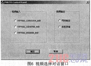
It can be selected according to the specific conditions of video input and video output:
(1) Video input: select among three options according to the resolution of the input video;
(2) Video output: Select between two options according to the video output flow direction.
Select and test different video input and output options separately, and observe indicators such as image quality and data flow.
4 Conclusions This scheme has the following features: It can realize the acquisition and compression of 1080i60 or SXGA high-resolution video; software controllable output rate adjustment; input image gain and contrast can be adjusted; rich video processing capability; Development is difficult. The high-resolution graphics image compression scheme designed by the scheme can ensure high-quality images, and has the characteristics of low code rate, high efficiency, small processing delay and reliable operation. It can meet the needs of high-resolution or multi-channel video coding, including video conferencing systems, security surveillance, civil aviation management and maritime.
Fiber Splice On Connector now available in SC, LC, or FC variants, which is catering for 250um to 900um, and 2.0mm, 3.0mm diameter single mode and multimode fiber types, including Multi-mode 62.5/125um and Multi-mode 50/125um. The single-mode versions of fiber splice on connector are available with PC or APC ferrules. Fiber splice on connector allows the installer to terminate and make connection in minutes at equipment and fiber patch panels. Fiber splice on connector removes any requirement for epoxy, adhesives or costly curing ovens, with features of high installation quality, high success rate and high reliability.Assembly of fiber splice on connector needs only normal fiber preparation tools: a fiber stripping tool, wipes and a fiber cleaver.Installation of fiber splice on connector is very fast and easy.
Fiber Splice On Connector
Fiber Splice On Connector,Butt Connectors,Wire Connectors,Wire Tap Connector
Foclink Co., Ltd , http://www.scfiberpigtail.com