1 Introduction
At the same time of rapid development of instrumentation, computer and network technologies are also developing rapidly. PCs have entered a period of rapid growth from high-speed growth to a stable development period. The era of purely electronic industry led by PCs has become a history, the emergence of embedded systems and Widely used, computers and networks have entered the post-PC era. Based on the embedded intelligent instrument remote monitoring system as one of the important development directions of industrial control network, it is the result of the common development of various technologies such as industrial data communication and control network technology and Internet technology [1]. The development and maturity of this technology will have a profound impact on people's production and life.
2 embedded controller hardware design
Controller definition: The embedded controller takes the high-speed processor as the core, and the electronic device or device controlled by the high-speed processor and other chips can complete various automatic processing tasks such as monitoring and control [4]. The embedded controller is the core part of the system.
2.1 system hardware structure diagram
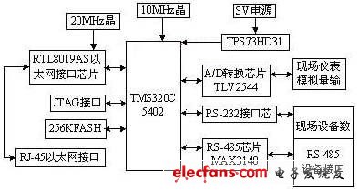
Figure 1 Embedded controller system hardware structure
The system hardware structure of the embedded controller is shown in Figure 1. Powered by 5V, 3.3V and 1.8V DC power supplies. The system is mainly composed of DSP chip TMS320C5402, 256K FLASH memory, Ethernet interface chip RTL8019AS, A/D conversion chip, serial port chip and so on.
From the system hardware structure diagram of the embedded controller, it is seen that the embedded controller is a key part of the embedded remote monitoring system. On-site intelligent instrumentation can input signals through the analog and digital interfaces of the embedded controller. The service program embedded in the controller can be used to view the signals of the on-site smart meters remotely by the client program through Ethernet or Modem. Control, thus enabling remote monitoring of smart meters.
2.2 processor DSP 5402 minimum system design
(1) Reset circuit. At the same time, the power-on reset circuit and the manual reset circuit are designed, which can be conveniently reset manually when a fault occurs during system operation. On the one hand, the reset circuit should ensure that the reset low time is long enough to ensure reliable reset of the DSP; on the other hand, it should ensure good stability and prevent the DSP from being reset by mistake. The reset circuit uses the MAX706R chip to form an automatic reset circuit. The MAX706R is an auto-reset chip that matches a DSP chip with a 3.3V operating voltage. The specific connection of the chip is shown in Figure 2.
(2) Clock circuit. The external clock input is often used in general DSP systems, because the clock is highly accurate, stable, and easy to use when using an external clock. Since the DSP work is based on the clock, if the clock quality is not high, the reliability and stability of the system are difficult to guarantee. Therefore, the system intends to use an external clock source to provide the clock, as shown in Figure 3. The external clock signal is directly applied to the X2/CLKIN pin of the DSP chip, and the X1 pin is left floating. Set CLKMEI=1, CLKMD2=1, CLKMD3=1. After reset, the clock of the DSP chip is 1/2 of the external crystal frequency, that is, divided by 2.
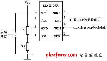
Figure 2 system automatic reset circuit 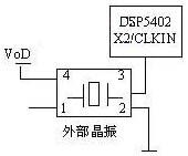
Figure 3 clock circuit
(3) System power supply design. The TMS320VC5402 chip is powered by dual power supplies. The core voltage and I/O interface voltage of the DSP are 1.8V and 3.3V respectively. This system requires three power supplies with voltages of 5V, 3.3V and 1.8V. Among them, RTL8019AS network card chip and analog-to-digital conversion circuit are powered by 5V power supply. The dual power solution of DSP is implemented by TPS73HD318. The input power supply voltage is 5V, the output voltage is 3.3V and 1.8V respectively, and the maximum output current of each power supply is 750mA.
2.3 Program Memory Extension
Compared with EPROM, FLASH memory has higher performance and price ratio, and is small in size, low in power consumption, electrically erasable and easy to use, and 3.3V FLASH can be directly connected to the DSP chip. Therefore, using FLASH as a program memory to store programs and some fixed data is a good choice. The program memory of this system uses a piece of AT29LV020 FLASH memory. The chip has 256K & TImes; 8 storage space, the fastest read speed is 100ns. Therefore, when reading the program, the main frequency should be lower than 10MHz.
2.4 interface circuit design
(1) Analog input interface. The analog input channel uses the TLV2544 chip produced by TI. When connected to the DSP chip, a frame sync signal FS can be used to control the start of a serial data frame. The TMS320VC5402 provides a high-speed, bidirectional, multi-channel buffered serial port MCBSP for direct connection to serial A/D converters.
(2) Ethernet expansion interface. To achieve the remote monitoring system of embedded smart meters, the first problem is to make the smart meter have an Ethernet interface. The RTL8019AS Ethernet interface chip produced by Taiwan Realtek allows the embedded controller to have a network interface of a general-purpose computer.
(3) RS-232 serial interface design. RS-232-C does not define the physical characteristics of the connector, so there are many types of connectors such as DB-25, DB-15 and DB-9. In order to connect to the serial port of the field smart meter, we use MAXIM111 of MAXIM to complete the conversion of level and logic relationship between EIA and TTL circuits.
(4) RS-485 serial communication interface. RS-485 is a serial communication bus standard developed to meet the needs of long-distance, distributed control systems. It supports multi-node, long-distance transmission. The RS-485 standard uses a balanced transmit, differential receive data transceiver to drive the bus. In order to expand the number of terminal connected devices, this design adds an RS-485 interface. The connection between the DSP and the RS-485 serial port is done using MAXIM's MAX3140UART communication chip.
Top features include:
- Constant Voltage or Constant Current modes
- Protection: Short circuit / Over-voltage / Over-temperature
- High Efficiencies: Up to 92%
- IP65 and IP67 designs for dry, damp or wet locations
- Fanless design: Cooling by free-air convection
- UL Cdertified for US and Canada; FCC Class B
- 5 year warranty!
Multiple Options Available for Each Model
- A-type: IP65 rated; Round high Bay Driver, Constant current level can be adjusted through internal potentiometer
- B-type: IP67 rated and built-in 3-in-one dimming function (0-10Vdc, PWM signal or resistance)

200-480Vac High Voltage Input LED Driver
High Voltage Input LED Driver,480V industrial High Voltage Driver,LED Driver High-bay Environments Application,IP67 LED Drivers
ShenZhen Fahold Electronic Limited , https://www.fahold.com