This paper introduces a method for debugging asynchronous motor speed sensorless AC speed control system using MATLAB and CCS. Using the powerful analysis and drawing functions of MATLAB language, combined with the advantages of DSP high-speed computing, the speed-adjustment experiment was carried out on the self-built sensorless vector control system platform. The experimental results show that the method of Matlab debugging and direct target code generation is adopted. It can avoid the complicated programming process of traditional computer simulation, reduce the workload, help to improve the overall efficiency of the system, and maintain the system's good dynamic and static speed control performance.
1 IntroductionMatlab is a powerful analysis, calculation and visualization tool, especially suitable for analysis and simulation of control systems. However, because the platform it depends on is the computer and its CPU, the execution speed of the MATLAB program is relatively high due to the power consumption of the CPU system. The input/output of high-speed signals appears to be slow, far from meeting the requirements of real-time signal processing. The DSP has similarities with the programming method of the microcontroller and computer CPU in terms of its software programming ability, but the DSP is more specific than the microcontroller. The operation speed is much faster, and it is much lower than the CPU power consumption and design complexity, but its analysis and visualization capabilities are far less than Matlab, and the development process is more complicated. However, there is a new technology that can closely combine DSP and Matlab, and make full use of their strengths to effectively promote the realization of the control system.
The servo drive device is an important part of the control system of the shaftless drive [3] of the printing press. Most of the domestic products use the special frequency converter with speed sensor to adjust the speed, the control precision is not high [4], and the price of foreign products is Very expensive, therefore, this paper developed a PI sensor-free speed sensorless vector control system, and carried out the speed control experiment on the self-built experimental platform. In the experiment, the mixed programming of Matlab and DSP was used. The debugging method, the experimental results show that the Matlab debugging and direct object code generation method can avoid the complicated programming process of traditional computer simulation, reduce the workload, help to improve the overall efficiency of the system, and maintain the system's good dynamic and static tuning. The speed control performance satisfies the requirements of the shaftless transmission control system of the printing press.
2. Introduction of speed sensorless vector control systemSince the high-performance vector control method is adopted and the speed sensor is defaulted, how to accurately obtain the rotational speed information and maintain the high control precision of the servo system to meet the requirements of real-time control has become an important direction of this research. Here we use the PI adaptive control method [9] to estimate the motor speed using the error signal of the q-axis current in the synchronous shaft system [9-10]. The overall structure is shown in Figure 1. The error between the angular velocity reference value ω* and the estimated angular velocity feedback value ω is sent to the speed regulator. The output of the speed regulator is the given value of the electromagnetic torque te*, and the q-axis of the current can be calculated by iq1 = LrTe/PmLmФd2 The component reference value iq1*, when the q-axis current does not reach the set value, can be adjusted by the q-axis voltage generated by Rs and the d-axis voltage generated by ω1σLs. Therefore, the error signal of iq1* and the actual value iq1 of the stator current q-axis component is fed to the output uq1' of the PI regulator regulator, which is the adjustment amount of the stator voltage q-axis component caused by the stator current q-axis component error.
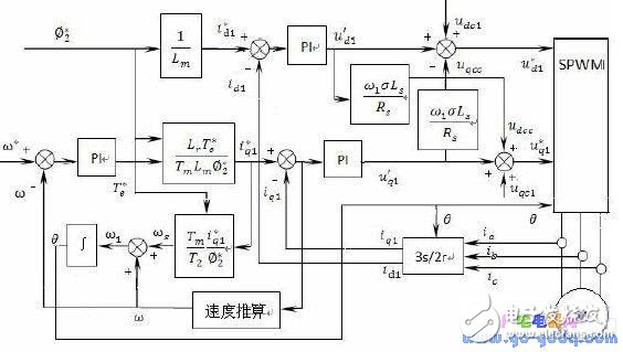
Figure 1 Block diagram of the algorithm principle
The speed estimation module takes the rotor flux linkage equation and the coordinate transformation equation which do not contain the real rotation speed as the reference model, and adopts the PI adaptive law containing the speed to be recognized as the adjustable model, and uses the stator current torque component as the comparison output, and adopts the ratio. The integral adaptive law performs speed estimation. After PI adjustment, the output is the motor speed to be sought. This method has a small amount of calculation, a simple structure, and is easy to implement.
3. Matlab and DSP mixed programming debugging methodIn the traditional development process, MATLAB is always used for simulation. When the simulation results are satisfactory, the algorithm is modified into C/C++ language and implemented on the hardware DSP target board. To find the deviation, you need to use Matlab to correct the algorithm, and then write the modified algorithm program on the DSP. This process is repeated, and it is very inconvenient to switch back and forth between the DSP development tool and the Matlab workspace. When the system is more complicated, it is necessary to step-by-step verification of each intermediate result and final result.
If you can connect Matlab with the DSP integrated development environment CCS and the target DSP, and use Matlab's analysis capabilities to debug the DSP code, then operating the TI DSP's memory or registers can be as simple as manipulating Matlab variables. The use of the toolkit Matlab Link for CCS Development Tools can solve the above problems. With this toolbox, the operation of CCS can be completed under the Matlab environment, that is, the entire target DSP is transparent like Matlab, and all operations are only utilized. Matlab commands and objects are simple, convenient, and fast. The following is an example of debugging the above-mentioned speed sensorless vector control system to illustrate the application of the Matlab-DSP integrated development environment in the control system. Input Simulink in Matlab command window, open Simulink module window, establish model of asynchronous motor vector control variable frequency speed control system [12], as shown in Figure 2, the structure is simple and clear, all modularized, easy to expand, according to actual needs , change the parameters of each module.
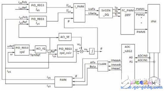
Figure 2 Block diagram of the algorithm principle
Next, set the simulation parameters and the Real-TIme Workshop option to compile the simulation model. And use Matlab Link for CCS Development Tools to establish a connection with the target DSP. With the CCSLink tool, data can be transferred from CCS to the Matlab workspace, data from Matlab can be transferred to CCS, and RTDX (Real-Time Data Exchange Technology) can be used between Matlab and real-time DSP hardware. Establishing a connection, transferring data between them in real time without stopping the program running on the DSP, this function can provide us with a window to observe the real-time running status of the DSP during the running of the program, which greatly simplifies the debugging work. The relationship between Matlab, CCSlink, CCS and hardware target DSP is shown in Figure 3.
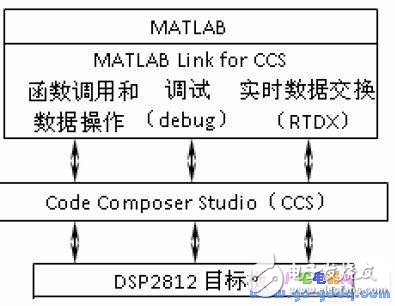
Figure 3 CCSlink connects Matlab with CCS and target DSP
We can modify a parameter or variable in Matlab and pass the modified value to the running DSP so that the processing algorithm can be adjusted or changed in real time, and the program can be debugged by observing the probe point data. Finally, combining CCSlink and Embedded Target for C2000 DSP Platform., the executable code of DSP2812 can be generated directly from the debugged Simulink model and loaded into the DSP target board, so that we can complete the system algorithm in the same Matlab environment. Design, simulate, debug, test, and ultimately run on the DSP2812 target board.
4. System debuggingThe hardware structure of the test bench [14-15] is shown in Figure 4. The inverter system uses DSP as the arithmetic control unit, uses the IPM module as the power circuit switching unit, and uses the Hall current sensor to detect the two-phase current of the three-phase motor. After the DSP controller performs corresponding operation processing on the detected current signal, the three pairs of SVPWM pulse signals generated by the PI control algorithm are applied to the IPM to drive the asynchronous motor, and the frequency of the output pulse signal is changed to realize the frequency conversion of the asynchronous motor. Speed ​​regulation.
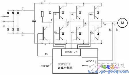
Figure 4 system overall structure block diagram
The motor parameters are: Rs = 10 Ω; Rr = 5.6 Ω; Ls = 0.3119H; Lr = 0.3119H; Lm = 0.297H; P = 4; J = 0.001kg.m2
Through the connection between DSP and CCS, the memory data of the target DSP can be accessed in the Matlab environment, and then the data can be accessed by Matlab's powerful analysis and visualization tools, and the compilation, linking, loading and running of the project can also be realized. Set breakpoints and probes, and finally load the target code generated by the satisfactory debug results directly onto the lab bench. The speed input is set to a step function, and the motor is operated with the rated load. The dynamic response curve obtained is shown in the figure below.
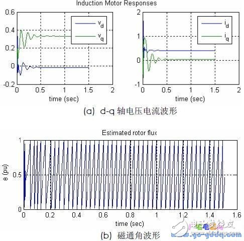
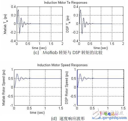
Figure 5 Experimental results
It can be seen from Fig. 5 that the dq axis voltage current and the flux angle response curve are stable. In the dynamic process, the motor torque in the Matlab environment [10] is basically the same as the torque curve in the actual DSP experimental platform [11-13]. The system responds quickly and the overshoot is small. It only needs 0.6S to achieve stability. The step response of the speed is shown in Figure 5(d). The system has some fluctuations when the motor starts, but under the action of the PI adaptive controller, only 0.5S system can reach the steady state, and the speed observer is proved. The lower speed can better track the actual speed change, and the actual speed is equal to the simulation speed value at steady state.
5 ConclusionThe DSP integrated design method proposed by Matlab in this paper is indeed feasible. The experiment proves that the operation of the DSP target board can be completed in this environment, including accessing the DSP memory and registers, and using the powerful tools of Matlab to the data in the DSP memory. Analysis and visualization are performed, so the system structure is simple, the debugging workload is small, and it is easy to implement. At the same time, the PI speed estimation method with certain adaptive ability can make an accurate estimation of the motor speed. The experimental results verify the correctness and feasibility of the system design.
Customized Laboratory Testing Instruments
Wuxi Lerin New Energy Technology Co.,Ltd. , https://www.lerin-tech.com