Hello, everyone, and it's time for a day of study. Today we'll talk about FPGA-based CRC generators. Let's take a look at the specifics below and welcome everyone to exchange and learn together.
1. Overview CRC, or Cyclic Redundancy Check, is a common channel coding technique used in digital communications. Its characteristic is that the length of the information segment and the check field can be arbitrarily selected.
2. The basic principle of CRC check:
The CRC code consists of two parts, the former part is the information code, which is the information that needs to be checked, and the latter part is the check code. If the CRC code length is n bit in total and the information code length is k bit, it is called (n,k ) code, the remaining r bit is the check digit. Such as: (7,3) code: 110 1001, the first three 110 for the information code, 1001 for the check code.
3 check code generation rules:
1) The original information code left shift r bit, the right side of zero, such as 110 -> 110 0000;
2) Divide 1100000 into g(x) (note that modulo 2 division is used, see below) and the remainder is the CRC checksum;
3) The check code is continued to the tail of the information code to form a CRC code.
4. About the generator polynomial g(x)
Divide operations are used when generating CRC checksums. Generally speaking, this is cumbersome. Therefore, the binary information is converted into a certain format in advance. This is the polynomial representation of the CRC. Binary numbers are expressed as coefficients of the generator polynomial, as follows: 
All binary numbers are represented as a polynomial, and x is only a sign of the symbol position. Therefore, we do not care about the value of x. We call it a code polynomial. (I have not studied the CRC algebra inference process, did not appreciate the convenience of using polynomial calculations, here we must learn is to give the generator polynomial g (x), can write the corresponding binary can)
Common generator polynomials are as follows: 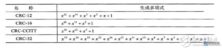
5. About modulo 2 division
Modulo 2 operation means addition does not consider carry, subtraction does not consider borrow.
1) Addition:
0+0=0 0+1=1 1+0=1 1+1=0
For example 0101+0011=0110, vertical column calculation:
0 1 0 1
+ 0 0 1 1
──────
0 1 1 0
2) Subtraction:
0-0=0 0-1=1 1-0=1 1-1=0
For example, 0110-0011=0101, vertical column calculation:
0 1 1 0
- 0 0 1 1
──────
0 1 0 1
3) Multiplication
0×0=0 0×1=0 1×0=0 1×1=1
The multi-bit binary modulo 2 multiplication is similar to the multi-bit binary multiplication in the ordinary sense, except that the latter uses the addition with carry when the intermediate result is accumulated, and the modulo 2 multiplication uses the modulo 2 addition with the intermediate result. . For example, 1011×101=100111, vertical column calculation: 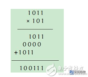
4) Division operation:
0÷1=0 1÷1=1
Multi-bit binary modulo 2 division is also similar to multi-bit binary division in the ordinary sense, but adopts different rules on how to determine the quotient problem. The latter is based on a binary subtraction with a borrow position. According to the remainder, the deductor is less than or not enough to determine whether the quotient 1 is still 0, if it is enough, the quotient 1 is, otherwise the quotient 0. Multi-bit modulo 2 division uses modulo 2 subtraction without borrowed binary subtraction, so it does not make sense to consider whether the remainder is enough to subtract the number or not. In fact, in the CRC operation, always guaranteeing that the first digit of the divisor is 1, the quotient of the modulo-2 division operation is determined by the modulo-2 division result of the first digit of the remainder and the first digit of the divisor. Because the divisor is always 1 in the first place, according to the modulo 2 division algorithm, then the first digit of the remainder is 1 to the quotient 1, and 0 is the quotient 0. For example, 1100100÷1011=1110...110, column vertical calculation: 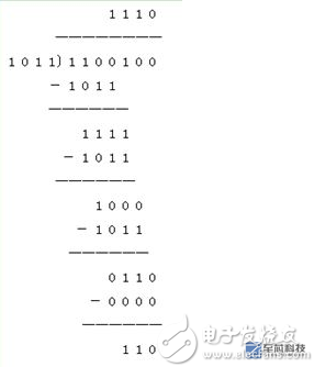
Having mastered the above algorithm, you can try to calculate a more complicated one, as follows: 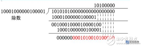
If the rest of the results are correct, what you have is enough.
6. Hardware implementation of CRC-CCITT
The generator polynomial of CRC-CCITT is: 
The corresponding binary number is the divisor in the above complex operation. From the previous calculations, it can be seen that for the 8-bit data 0xaa, its CRC is 0001 0100 1010 0000. The following verilog is used to see whether this result can be obtained:
To achieve this, we still need the LFSR circuit. Refer to the description of the circuit characteristics in "FPGA generates pseudo-random numbers based on LFSR." If you don't need to understand the principle, you can skip it directly. Some improvements are made. The pseudo-random number generator can be regarded as a Moore type state machine whose output is only related to the current state; at this time, using the LFSR circuit, the data input needs to be introduced, and the output depends not only on the current state but also on the input. Signal, equivalent to Mealy type state machine, as shown below: 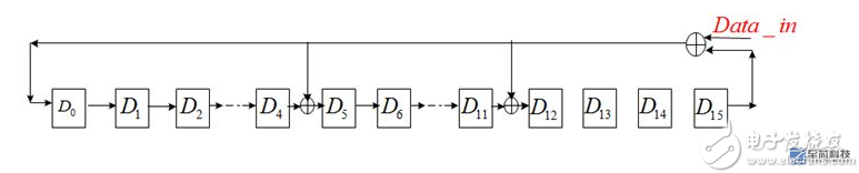
Note the difference between this feedback branch and the pseudo-random number generator!
The feedback term gr+1gr...g0 is the coefficient of the generator polynomial, still 1 represents the presence feedback, 0 represents the absence of feedback; this circuit can perform the above-mentioned modulo-2 division operation, if we require 0xaa CRC, then from After inputting 0xaa for 8 bits from the high bit to the low bit, the data in D15...D0 is the required remainder, which is the CRC check digit.
7.verilog description If you use the serial circuit to achieve the serial, 8 bit data to be shifted 8 times, you need 8 clk, inefficient, in order to be able to output results in a clock cycle, you must use a combination of circuits, of course, this is The space-for-time method, due to the use of the for loop 8 times, will inevitably increase the circuit scale by 8 times.
Module CRC_GEN(
Input rst, /*async reset,active low*/
Input clk, /*clock input*/
Input [7:0] data_in, /*parallel data input pins */
Input d_valid, /* data valid, start to generate CRC, active high*/
Output reg[15:0] crc
);
Integer i;
Reg feedback;
Reg [15:0] crc_tmp;
/*
* sequential process
*/
Always @(posedge clk or negedge rst)
Begin
If(!rst)
Crc <= 16'b0; /* The initial value in the trigger is very important */
Else if(d_valid==1'b0)
Crc <= 16'b0;
Else
Crc <= crc_tmp;
End
/*
* combination process
*/
Always@( data_in or crc)
Begin
Crc_tmp = crc;
For(i=7; i>=0; i=i-1)
Begin
Feedback = crc_tmp[15] ^ data_in;
Crc_tmp[15] = crc_tmp[14];
Crc_tmp[14] = crc_tmp[13];
Crc_tmp[13] = crc_tmp[12];
Crc_tmp[12] = crc_tmp[11] ^ feedback;
Crc_tmp[11] = crc_tmp[10] ;
Crc_tmp[10] = crc_tmp[9];
Crc_tmp[9] = crc_tmp[8];
Crc_tmp[8] = crc_tmp[7];
Crc_tmp[7] = crc_tmp[6];
Crc_tmp[6] = crc_tmp[5];
Crc_tmp[5] = crc_tmp[4] ^ feedback;
Crc_tmp[4] = crc_tmp[3];
Crc_tmp[3] = crc_tmp[2];
Crc_tmp[2] = crc_tmp[1];
Crc_tmp[1] = crc_tmp[0];
Crc_tmp[0] = feedback;
End
End
Endmodule
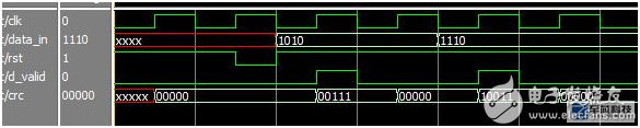
The simulation result is as follows: The CRC of the data 0xaa and 0xf0 is obtained. To verify the correctness of the result, you can manually calculate according to the modulo 2 rule. ^.^ 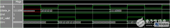
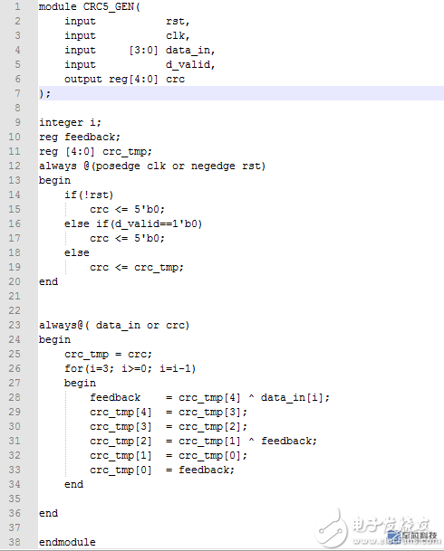
8. Also gives the program and simulation results of a (4,4) code with a 4-bit information bit, 5-bit CRC code. The flow of the program is exactly the same as above: 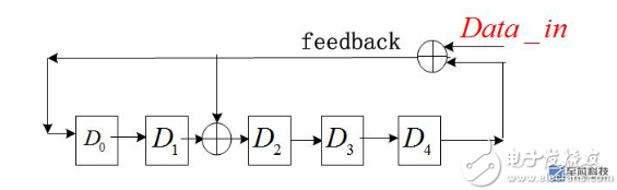
Postscript: Careful readers may find that this article avoids the reason why the LFSR circuit can perform modulo 2 operation, not because it is not told to you, because I am not very clear. The engineering background is a bit ignorant about mathematical reasoning. Cloud, especially when you read the formulas for several pages of domestic textbooks, if you have a simple explanation of the origin and application of LFSR circuits, it's a simple matter to explain, but please strongly recommend it. Thank you!
Talk to you today, everyone, come on.
Smart Shelf Edge Led Display,Shelf Led Display,Display Shelf Lighting,Led Shelf Display
ShenZhen Megagem Tech Co.,Ltd , https://www.megleddisplay.com