In the past, high-voltage connectors, low-voltage connectors and optical fiber connectors were installed separately in electronic equipment, but with the increase of high and low voltage and optical fiber terminals, the space required for installation will become larger and larger, and maintenance and maintenance are also more difficult . Modern and future wars have put forward requirements for miniaturization, integration and modularization of military electronic equipment, and the requirements are getting higher and higher. Many components of foreign advanced weapon systems have been integrated and modularized. Once there are problems, they can be used. The laptop computer is connected to the data detection system on the weapon equipment for online detection. After the detection, the damaged module can be replaced as a whole, so maintenance and maintenance are particularly convenient, saving maintenance time, and the battlefield is more survivable. In this context, many components of military electronic equipment have been integrated, and optoelectronic hybrid connectors have emerged at the historic moment, effectively solving the installation space and maintenance problems.
The connector in this article is mainly used for data connection of power supply, electrical signal and optical signal in electronic countermeasure equipment. Organic combination of high voltage connectors.
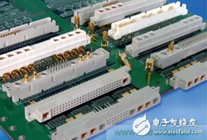
Picture title: photoelectric mixed connector
Main performance requirementsRated current: 1A (DC);
Contact resistance: ≤15mΩ;
Dielectric withstand voltage: 10kV (sea level) /6.5 kV (21000m) (four cores);
Leakage current: ≤10uA;
Rated working voltage: 5.6 (DC four cores) /0.3 (DC seven cores) kV;
Operating temperature range: -55 ℃ ~ + 125 ℃;
Single mode: 1310 / 1550nm; single head insertion loss: ≤0.3dB; reflection loss: greater than 45dB;
Product overall structure designThis connector belongs to the multi-core quick-release category. In order to prevent misinsertion, the plug housing and the socket housing are designed with a five-key slot structure; multi-core quick-release connectors use staples and screw sleeves to achieve quick connection and quick separation. The sleeve connects the plug connector to the socket connector and uses a corrugated spring locking mechanism to maintain a constant interface pressure. In order to achieve the purpose of quick separation, the plug shell is equipped with a connecting sleeve. The inner hole wall of the connecting sleeve is designed with three equal-pitch helical structure bayonet spiral grooves, and the bottom of the bayonet groove has a nail through hole The engagement of the connector can be observed; correspondingly, the surface of the socket shell is designed with three staples, which can be screwed to the bottom of the spiral groove. After the plug is screwed into place, the connector can be locked.
Due to the metal shell and EMI design, the reliability is high, and the high and low altitudes have excellent voltage resistance. The length of the cable can be adjusted arbitrarily according to different needs for field installation, and the application is more flexible.
The plug connector includes a connecting sleeve, a housing, a soft mounting board, a pin assembly, a jack assembly, an optical fiber contact piece containing a 1.25mm standard connector, and corresponding wires. The material of the mounting plate is silicone rubber, which is formed by die molding; the jack and pin conform to the regulations of GJB1216. The 20th contact piece is selected and is made of tin bronze car. The structure is a slotted two-piece type. Use stainless steel casing for protection. After the product is assembled, the tail is bonded and sealed with silicone rubber to ensure the voltage resistance of the product.
The socket connector includes a housing, a mounting plate, a pin assembly, a jack assembly, an optical fiber contact piece containing a 1.25mm standard connector, and corresponding wires. The material of the shell is thermosetting material DAP, which is formed by die molding. The design and structure of the insulating mounting plate have the correct cross-section and fillet radius so that it will not be damaged, cracked or broken during normal assembly and use. The design of the insulating mounting plate allows all contacts to be reliably fixed in the insulating mounting plate. When the product is assembled, it is filled with silicone rubber to block the air gap path and ensure the voltage resistance of the product.
Guangzhou Bolei Electronic Technology Co., Ltd. , https://www.nzpal.com