The overvoltage protection circuit for the power supply is illustrated as follows:
Figure (a) presents a simple and effective overvoltage protection design. It utilizes a Zener diode, Dz, to limit the power supply voltage applied to the operational amplifier within a safe range. The Zener diode's operating voltage should be selected based on the formula: Vz ≤ 2Vsmax. Ideally, Vz should be as close as possible to or equal to the total power supply voltage. A high-power resistor R should be used as the current-limiting resistor, ensuring stable operation of the voltage regulator.
Figure (b) offers both overvoltage and transient overvoltage protection. Under normal conditions, the voltage drop across FETs J1 and J2 is very low, so the ±VSD value remains small, and the Zener diodes Dz1 and Dz2 do not conduct. However, when the power supply voltage becomes too high, the Zener diodes break down, stabilizing the op amp’s positive and negative supply voltages. The reverse current from Dz1 and Dz2 flows through J1 and J2, increasing their VDS voltage and limiting the voltage applied to the op amp. Capacitors C1 and C2 are used to suppress sudden voltage spikes, as capacitors cannot change voltage abruptly. With large capacitance values, the voltage fluctuations across C1 and C2 will be minimal, effectively filtering out transients.
Both circuits provide reliable overvoltage protection for single-supply systems. Choose the one that best fits your specific application requirements. 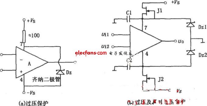
Substation Structures,Telegraph Pole,Substation Steel,Substation Steel Structures
JIANGSU HONGGUANG STEEL POLE CO., LTD. , https://www.hgsteelpoles.com