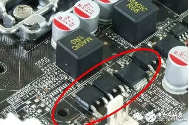
The MOSFET, or Metal-Oxide-Semiconductor Field-Effect Transistor, is also known as a Metal-Insulator-Semiconductor device. One of its unique characteristics is that the source and drain can be reversed. Both are N-type regions embedded in a P-type substrate. In most cases, these two regions are identical, and even if their positions are swapped, it typically doesn't affect the performance of the device. This symmetry makes them suitable for various applications where bidirectional operation is needed.
Currently, the largest application area for MOSFETs is in consumer electronics power adapters. The second major area is in computer motherboards, laptops, computer power supplies, and LCD displays. As technology advances, the demand for MOSFETs in computer components and display systems has surpassed that of traditional consumer electronics. Power adapters, once the main users, now see a declining trend in MOSFET usage.
Thirdly, MOSFETs are widely used in network communication, industrial control, automotive electronics, and power equipment. These sectors place high demands on MOSFETs, especially in the automotive industry, where the need for MOSFETs is rapidly catching up with that of consumer electronics.
The following six common causes of MOSFET failure are summarized, followed by an analysis of the top two issues:
1: Avalanche failure (voltage failure) – this occurs when the voltage between the drain and source (BVdss) exceeds the rated voltage of the MOSFET, leading to failure due to excessive energy.
2: SOA failure (current failure) – this happens when the current (Id) exceeds the safe operating area (SOA), causing excessive power loss and thermal stress that leads to failure.
3: Body diode failure – in circuits like bridge rectifiers or LLC topologies, the body diode may fail due to damage or overloading.
4: Resonant failure – during parallel operation, parasitic inductance and gate circuit parameters can cause oscillation and lead to failure.
5: Static failure – often occurs in dry seasons like autumn and winter, caused by electrostatic discharge from humans or equipment.
6: Gate voltage failure – abnormal voltage spikes on the gate can damage the gate oxide layer, leading to failure.
Avalanche Failure Analysis (Voltage Failure)
What exactly is an avalanche failure? Simply put, it happens when the voltage across the drain and source of the MOSFET exceeds its rated voltage due to factors such as bus voltage, transformer reflection voltage, or leakage inductance spike voltage. This results in a failure mode where the energy level reaches a critical threshold, causing the device to fail.
The image below shows the equivalent schematic of an avalanche test. For power supply engineers, this should be easy to understand.
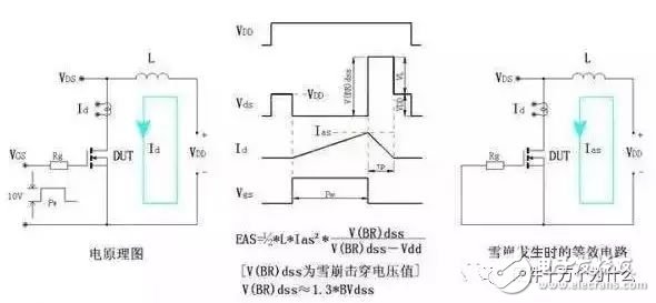
When we request failure analysis from manufacturers, they often just say "EAS" or "EOS." But how do we confirm if it's actually an avalanche failure? By examining the waveform of the failed device, we can compare it to known patterns and determine whether it was caused by an avalanche event.
Preventive Measures for Avalanche Failure
Since avalanche failure is primarily a voltage-related issue, the focus should be on voltage management. Here are some practical steps:
1: Apply proper derating—industry standards usually recommend 80%-95% derating, depending on the company’s warranty policy and design considerations.
2: Optimize the transformer reflection voltage to avoid unnecessary voltage spikes.
3: Design effective RCD and TVS snubber circuits to absorb transient voltages.
4: Use thick and short wiring for high-current paths to reduce parasitic inductance.
5: Choose an appropriate gate resistance (Rg) to control switching behavior.
6: In high-power applications, add RC damping or Zener diodes to further suppress voltage transients.
SOA Failure (Current Failure)
The second type of failure is SOA (Safe Operating Area) failure. It occurs when both high current and voltage are applied simultaneously to the MOSFET, leading to transient heating. If the chip, heat sink, and package cannot dissipate the heat quickly enough, thermal accumulation may occur, eventually leading to thermal breakdown.
The diagram below shows the SOA limits for different conditions:
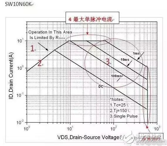
1: Limited by maximum rated current and pulse current
2: Limited by RDSON at maximum temperature
3: Limited by maximum power dissipation
4: Limited by maximum single-pulse current
5: Limited by breakdown voltage BVDSS
As long as the MOSFET operates within these limits, it can effectively prevent power failures caused by overcurrent or overvoltage.
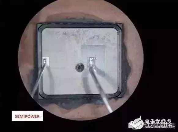
This is a solution for an atypical SOA failure that might not be obvious at first glance, such as when aluminum layers are removed.

Preventive Measures for SOA Failure
1: Ensure that all power constraints remain within the SOA limit under worst-case scenarios.
2: Implement precise and accurate OCP (Overcurrent Protection) functionality. Engineers often set a 1.1–1.5 times current margin before determining the RSENSE resistor value based on the IC’s protection voltage (e.g., 0.7V). Experienced designers also consider detection delay time and the impact of CISS on OCP. Another important parameter to consider is Td(off), which affects how quickly the MOSFET turns off after detecting overcurrent.
Let’s look at the FLYBACK current waveform below (click to enlarge for better visibility).
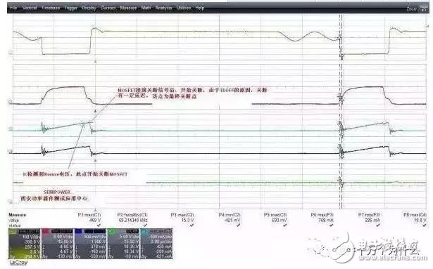
As shown, when the current approaches the peak, there is a slight drop. After this point, the current rises again. This rise time is the time it takes for the IC to detect the overcurrent signal and turn off the MOSFET. However, due to the inherent turn-off delay of the MOSFET, the current can experience a secondary rise. If this secondary rise is too large, it could cause magnetic saturation in the transformer, leading to a current surge or exceeding the device’s specifications.
3: Ensure sufficient thermal design margin. This is a standard practice in most companies, with strict adherence to derating guidelines. Adding radiators can help but should be done carefully to avoid overheating or mechanical stress.
Disposable vapes,Cigarrillo electrónico desechable, Jetable Cigarette électronique,Disposable wapes oil Atomizer,Elektronische Ezigarette
Shenzhen Yingyuan Technology Co.,ltd , https://www.yingyuanvape.com