Recently, Tanabata is coming soon~ It’s time to give gifts to my sister~, so do something that is both creative, practical, and beautiful! Then this lunch box, which can automatically water the plants, is an ideal choice.
First put the finished product map:
On the left is the soil moisture probe. When the soil is dry to a certain value, open the solenoid valve for watering.
On the left is the DC power line (DC5.5*2.1mm) with 5V input. You can use USB to DC directly for power. On the right is the water inlet, which is directly connected to the faucet.
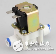
The solenoid valve uses the solenoid valve of the water dispenser, and costs about 10 yuan. The voltage is 12V, so you need to purchase another boost module.
The top is the boost module, followed by the soil moisture detection module, DHT11 temperature and humidity module.
LCD1602, can display the current running time, high temperature and humidity, and soil moisture value.
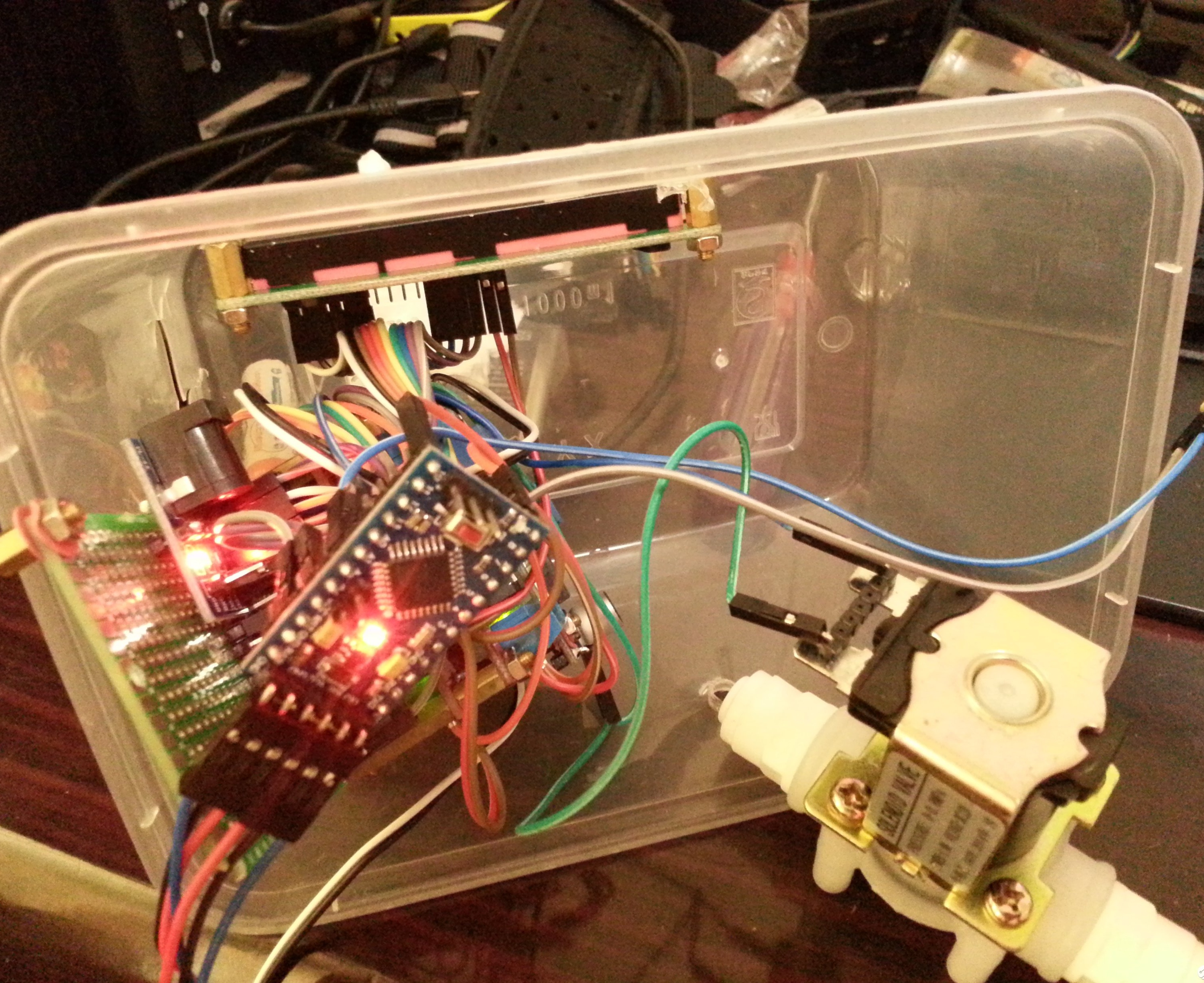
It looks like this:
Top view. One of the two white pipes is the water inlet, one is the water outlet, and the inside is the solenoid valve control.
The program structure is also very simple:
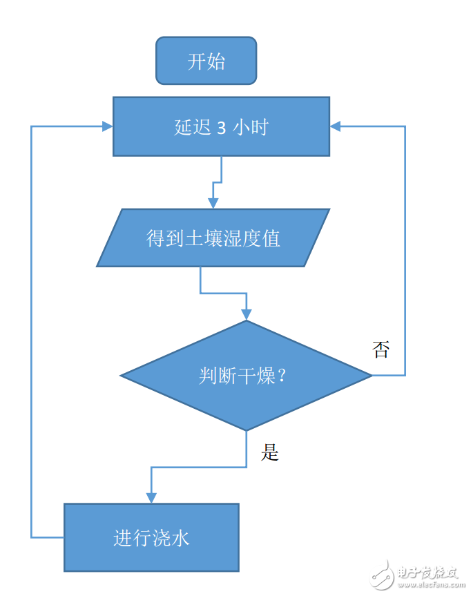
When the soil moisture probe detects that the soil is dry, open the solenoid valve for watering, close the solenoid valve, and then continue the test, so that it will continue in an infinite loop. The judgment is made every 3 hours.
This is a design drawing (a very preliminary idea, the actual implementation has some subtle differences from this figure):
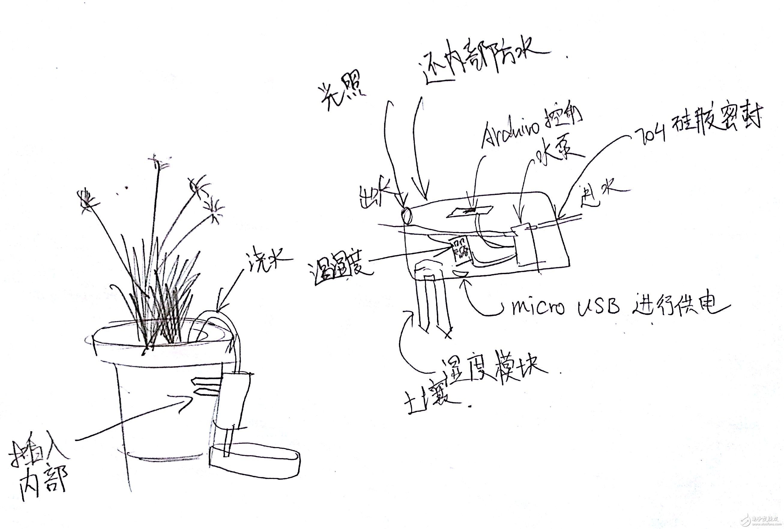
(Forgive my soul style → _ →)
There are two options for how to water:
Option 1: Use a solenoid valve to directly pour tap water.
Option 2: Pump water using a pump.

It has been tangled for a long time when choosing a practical pump or a battery valve. Finally decided to use the battery valve, because if you use a water pump, you must put a special basin to fill the water ... and manually add water to the basin, not a once-and-for-all solution
(Yes, I am so lazy... (╯‵□')╯(â”»â”â”»)
First look at the material list:
(You didn't guess wrong, I just threw things at once, then took a photo...)
Then make a power supply module, one row connected to the positive pole and the negative pole, used to supply power to various modules. (Because I didn't buy arduino's Shields, I can only do this)
The hole size of this universal board is M2, and I am forced to expand to M3 size before I can screw the M3 copper column.
Then visually check the placement, mark it, and prepare for drilling:
Direct electric hand drill, in fact, to drill this plastic, it feels that the heat generated by the friction melts the plastic, not the actual hole drilled... so there are a lot of raw edges.
Screw on the screw.
The LCD 1602 is fixed below:
Find the approximate location and mark it
Punch, screw (in fact, this hole I still snored... but the plastic box can have a certain deformation, so it is still forced to screw it up.)
Snoring hole...
Still forced to screw it up.
This interface of the relay can be directly plugged in with the DuPont line, as long as the black plastic head of the DuPont line is removed. There is no need to buy a special line.
DuPont line can be solved! save money!
Regarding the handling of the DuPont line, use the utility knife to lift the bulge of the DuPont line head card:
It can be taken out very easily.
Then you can insert the exposed metal part.
Then install the relay, endless punching... screw
In fact, it is a bit embarrassing, but it doesn't matter.
Then suddenly I felt that the lunch box was too big, and every module had to punch me like this, the efficiency was too low...
Then went to sleep. When I was sleeping, the inspiration came, and I changed my mind. (Yes, all I did before was pushed to redo!)
The next day, holding a bunch of modules, study how to assemble scientifically...
then……
.
. .. .. After ten minutes, the two are stacked together.
. .. .. .. After twenty minutes (busy, forget to take a photo →_→)
Duang~~ This is the finished product! The multi-layer structure is adopted, the layout is reasonable, and the structure is exquisite (the magic BGM is fucked: my friend, I want to tell you proudly, oh, I am really good, I am really good.)
Because it is used for watering, the entire board is stationary (this is not a smart car!), so the structural strength of the connection is not a primary concern.
The following multi-angle shows, from top to bottom, the real-time clock module DS1307, temperature and humidity module DHT11, soil moisture sensor, and boost module (used to obtain 12V output).
A copper column has been reserved and can be easily fixed on the universal board.
This way... I can hold you in the palm of my hand~( ̄『 ̄)
Then the next step is to fix it to the universal board, the right side is used to put the solenoid valve, and the middle gap can weld two rows of pins for powering various modules.
There is a very coincidental place. The width of this universal board is exactly the same as the length of the relay module. The hole in the corner is completely opposite. Obsessive-compulsiveness is very comfortable.
By the way, the size of the board is 5x7
To fix this stack of modules, you only need to drill two holes. Use a small knife to engrave the position to be drilled to avoid the drill collar (that is, a mark engraved between Q and R in the figure):
Warning: For fiberglass board cutting and drilling, be sure to pay attention to dust pollution!
It is very dangerous to inhale these dusts. So I put the whole circuit board into the water for drilling. (The process did not take the phone to take pictures because of the water)
Before preparing to drill, throw all the modules into the lunch box and test the layout:
The size of the lunch box is 1000ml:
Ok, everyone, I got back from the hole. This time the drill is good, it can be right, the error is not very big.
Decorate the screw and feel it:
Then plan to weld two rows of pins here, one row connected to the positive pole and the other row to the negative pole.
Then remove the other modules and concentrate on soldering the board:
Put on the component:
Prepare for welding:
Then this is the effect... smooth and round solder joints? The minister can't do it!
...... I admit that I am not at all in the soldering circuit, so I don’t want to spit this solder joint ugly ==
Finally, I measured it with a multimeter and it works, so there is no problem.
Of course, I have to get a good job of welding: so I put it on again (I feel that I have wasted a lot of time when I removed it and installed it...)
Then, by soldering the two pin headers to the solenoid valve, the DuPont line can be directly inserted, so that the various modules are independent, and it is convenient to disassemble later. (To ensure that the interface is unified, it is convenient to call!)
The solder joint is like this... In fact, here is the solder joint, I later re-welded it again =_=. So seeing such a round solder joint is generally a virtual solder.
Then one day passed... Everything was thrown a bunch before going to sleep at night.
The third day is up~ Today we explain how to write the program for arduino pro mini, use FT232RL, and the arduino pro mini directly connect the six pins one by one (very convenient):
If you supply arduino separately, you only need to connect three pins. But remember that the two chips have to be shared, otherwise they will not be able to pass.
The first connection is the LCD1602, the corresponding circuit diagram is like this:
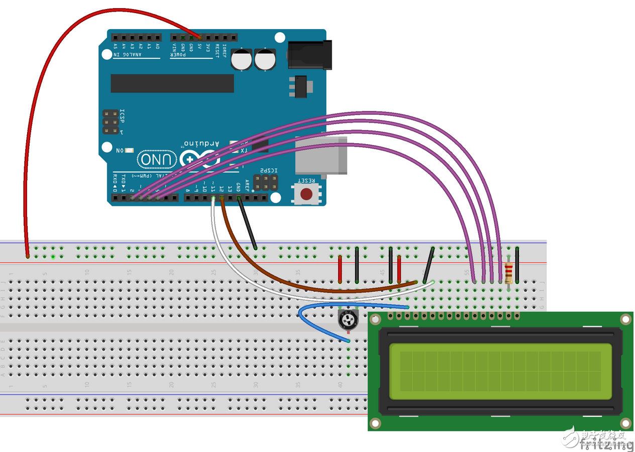
According to the pin definition of LCD1602, the connection method with arduino is as follows:
LCD VSS ground
LCD VDD is connected to 5V power supply
The LCD VL is used to adjust the contrast and is grounded through the potentiometer.
LCD RS pin link digital port pin12
LCD R/W pin ground
LCD Enable pin link digital port pin11
LCD D4 pin link digital port pin5
LCD D5 pin link digital port pin4
LCD D6 pin link digital port pin3
LCD D7 pin link digital port pin2
LCD BLA source positive
LCD BLK light source negative
But I slightly modified the position of the pins for easier wiring:
RS-"8
Enable - "7
D4 - "6
D5-"5
D6-"4
D7-"3
R/W-"GND
Then the connection is so dense that there are so many lines:
Then connect the DHT11 module, VCC and GND to the power supply and ground, and OUT to the 2nd digital port.
Then connect the potentiometer, COM and NO are the two ends of the switch:
Can be easily inserted~
Fully inserted (cannot expose too much metal):
Tighten the screws and you're done:
There are too many lines here, but also to connect with pliers...
The two relays are connected to the digital port No. 9 and the digital port No. 10.
Write a small program to test that both relay 1 and relay 2 can be switched normally.
It took a lot of time to connect the modules one by one. The two power supplies are independent, one power supply is long-term, and the arduino, relay 1, boost module, and LCD1602 are connected. The other power supply can be turned off, to the DHT11, the soil moisture module, the backlight LED of the LCD1602, and the relay 2 to supply power, usually turn off this part of the power supply, to achieve energy-saving purposes.
a dense connection line...
This is the real-time clock module DS1307, which is not actually used. So I took it down (it didn't use why you put people on it (╯‵□)) ╯(â”»â”â”»).
Then connect all the modules to the line and pre-assemble them to see if you can put them down:
In the position of planning the module, you have to mark it again... Punch:
Then punched out. The process is much the same as the previous one, so I won’t put the picture.
Then screw on the screw to see, there is a lot of blank space on the right, you can use it later to put the lithium battery, or move the power:
Top view:
Put a mobile power supply in, test it, just put it down.
The volume of the lunch box is 1000ML, forcing it to force!
Lights up the LCD backlight after power-on
Then debug the program again... so loop. The hard process of debugging the program is not recorded... The code is placed on github, and the address is at the bottom of the post:
Then link the water pipes. You can insert a 6mm hole directly with the drill.
The link looks good. Because this lunch box can be easily deformed, it is easy to adjust:
Closely integrated:
Found that the power cord could not be inserted, use a 1cm drill to open the hole:
1cm opening effect
Plug in the power cord, just plugged in
The overall effect, while entering the water, the other side of the water:
The water inlet is such a transfer interface that can be directly attached to the faucet without affecting normal use. A treasure search is ok (keyword: 2 points universal joint water purifier).
There is a switch on the top that can introduce water flow without affecting normal effluent.
Final display
Arduino pro mini chip
Updated list of items on August 10, 2015 at 09:37:32:
Arduino pro mini (or whatever else is compatible)
FT232RL (USB to serial port for programming arduino pro mini)
LCD1602 (for display)
DHT11 temperature and humidity module (only used to display temperature and humidity, the current program does not judge the watering capacity according to temperature and humidity data)
DuPont line (both 10cm and 21cm)
Universal board, solder, soldering iron. (If you use arduino uno plus sensor shield, you don't need to solder your own circuit)
Pin
DC connector (or micro usb connector for power supply)
DC power supply line
Solenoid valve (or pump)
Boost module / step-down module (select according to the voltage of the solenoid valve or pump)
Soil moisture detection module
Water pipe (I use 2 pipes, depending on the size of the solenoid valve or pump)
Faucet transfer interface (for solenoid valve solution, pump solution does not need to buy)
M3 screw, M3 copper column
Relay (if it is not solar powered, no need to save power, only one. If you use solar-powered solution, you can imitate my practice)
Photoresistance
Updated on August 13, 2015 at 15:09:30, adding a photoresistor:
If you search for "arduino how to connect the photoresistor", the result is generally to let you connect a resistor, and then connected with the photosensitive. In fact, this is not necessary, because there is a resistor inside the AVR microcontroller:

Just use this resistor just fine. Set an analog port to high
#define PHOTO_RESISTOR_PIN A2
pinMode(PHOTO_RESISTOR_PIN, OUTPUT);//Set the pin mode to output
digitalWrite(PHOTO_RESISTOR_PIN, HIGH);//Pull-up pin
Serial.println(analogRead(PHOTO_RESISTOR_PIN));//Debug output
One end of the photoresistor is connected to A2, and the other end is directly grounded. This structure is very simple. The measured value is 1023 under all black conditions, the value 623 is read by strong light flashlight, the outdoor cloudy environment (no direct sunlight), the reading value is 981, although it is not very accurate, but it is generally judged to be day or night. Still enough. Set the threshold to 1000. If the read value is less than this value, it means that it is daytime and no soil moisture is detected.
The environment is cloudy, there is no direct sunlight, and the value of the pin connecting the photoresistor is 981.
Also, when I was dismantled, I was too violent and broke the lunch box ==.
Two breaks... very serious, only change the lunch box.
Just put it, I went to buy a new lunch box tonight and repair it.
================ Split Line ==========================
Code download address: directly package ZIP download or visit github homepage
There is a file in the ino format, which is the file of the arduino program. To open with arduino software. Arduino software download
Although I use the arduino pro mini, in theory, boards such as arduino uno are compatible.
Next plan:
Add the function of judging the amount of watering according to the temperature. If the temperature is low, watering is less (I don't know if there is such a demand? It is said that some flowers can't be poured too much water in winter. There are children's shoes with many years of experience in flowering to teach some experience~)
Add tf card module. Write the value of the change in soil moisture to the tf card.
The photosensitive module is added, and light is detected and then watered.
This Wifi Backup Camera connects wirelessly to your smartphone allowing you to see the camera view on your smartphone screen! Download the free My Cam app from the App Store for IOS device or Google Play Store for Android device , the camera and smartphone will be able to connect via a WiFi connection .
1, Wifi Wireless Backup Camera system for Truck/Van/Caravan/Trailers/Camper/Pickup/5th Wheel/Bus. Easy to install, no more complex wiring.
2,Rearview IR Reverse HD backup Camera with Built-in Wireless Transmitter---with 12/18/28 individual Infrared (IR) LED for Night Vision. Hard Metal Cased Camera with IP68 Waterproof and Mud proof, Designed and tested for extreme climates.
3, Voltage Range From 12-32V DC Power, Flexible Vehicle Compatibility.
4, Digital wireless technology for specialty vehicles , No any interference with other wireless devices, if you ensure stable and high resolution image with 100M acceptance range in open areas.
Wifi Backup Camera
Wifi Backup Camera,Wifi Wireless Backup Camera,Wifi Wireless Backup Camera For Suv,Wifi Plate Frame Backup Camera
Shenzhen Sunveytech Co.,LTD , https://www.sunveytech.com