In recent years, the application of radio frequency identification (Radio Frequency of IdenTIficaTIo, RFID) technology has been widely used, and it has also received much attention. In particular, RFID systems in the UHF band have received more attention due to their long transmission distance and high transmission rate. A typical RFID system consists of an RFID reader and a tag. The RFID passive tag is powered by an electromagnetic signal emitted by the RFID reader and communicates with the reader through a modulated electromagnetic signal. Therefore, the advantages and disadvantages of RFID tag antenna design have a critical impact on its system performance.
Common RFID reader antennas have folded oscillator antennas, fractal antennas, microstrip antennas, and axial mode helical antennas. Since the folded vibrator antenna and the fractal antenna are generally linearly polarized antennas, it is difficult to meet the reader's identification requirements for electronic tags in all directions, so it is not applicable in many occasions; and the microstrip antenna is miniaturized due to its large size. The use of the reader in the handset is limited; the axial mode helical antenna is also too high in axial height and is limited in practical use. Therefore, how to design a small-sized, low-profile, high-performance circularly polarized RFID antenna has become the focus of attention. (How to make short wave antenna)
The four-arm helical antenna is widely used in the GPS field due to its excellent circular polarization. After further development, Wang-lk Son et al. applied a four-arm helical antenna to RFID and replaced the traditional monopole antenna with the planar inverted-F antenna as the antenna arm of the four-arm helical antenna, as shown in Figure 1. A good result. In this paper, an RFID reader antenna with advantages in size and performance is designed.
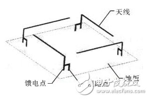
Figure 1. Inverted F-folded four-arm helical antenna
1. Design of miniaturized four-arm helical antenna
1.1. Design of four-arm helical antenna
The structure of the inverted F four-arm helical antenna designed in this paper is shown in Figure 2. The antenna consists of four identical inverted F antennas printed horizontally on a rectangular microwave composite dielectric plate with a dielectric constant of 9.6, a size of 60 mm & TImes; 60 mm and a thickness of 1 mm. Four FR4 small media plates with a thickness of 1 mm. The four antenna feeds are equal-amplitude feeds, and the phases are delayed by 90° in the counterclockwise phase to form a right-hand circular polarization.
Since the four arms of the helical antenna are close to each other, the distance between the two arms is about 0.18 λ, and the coupling between the four arms of the antenna is strong. Therefore, when matching on four separate ports, each port cannot be individually matched according to the traditional method, and the power division network is added. The coupling between the four arms should be fully considered. Simulations using Ansys HFSS reveal that the coupling between the opposite arms is much larger than the coupling between adjacent arms, as shown in Figure 3. Because the currents on the opposite arms are parallel to each other, the mutual influence is too large, and most of the currents on the adjacent arms are perpendicular to each other, so the influence is small, so only the coupling between the opposing arms is considered within a certain range. Assume that the four antenna arm ports are port 1, port 2, port 3 and port 4 in counterclockwise, and the reflection coefficients are Γ11, Γ22, Γ33 and Γ44, respectively. The coupling coefficients between the antenna arms are M13 and M24, due to the antenna. The symmetry between the two pairs of arms, so only the relationship between the antenna arms 1 and 3 needs to be analyzed. Assuming that the phase at port 1 is zero, the phase difference produced by energy transfer from port 1 to port 3 is θ, and the feed phases of port 1 and port 3 are 180° out of phase, then the energy coupled from port 1 to port 3 is at the antenna. The phase produced at the port 3 of the arm is -180°-θ. Since the antenna spacing is small and θ is small, it can be considered that the energy of the port 1 coupled to the port 3 is -180° at the port 3. The feed phase of port 3 is -180°, and the phase of its reflected energy is 180°. As seen at port 3, the energy delivered from the port contains the energy reflected by port 3 and the energy coupled to port 1. It has been found that the reflected energy and the coupling energy are 180° and -180° at port 3, respectively. When the energy of the reflection and the energy of the coupling are equal, the equal amplitude inversions cancel each other out to achieve the best matching effect, ie
Γ33=M13 (1)
Conversely, when Γ11=M13 is satisfied, the best match is reached at port 1. Similarly, port 2 and port 4 can be analyzed.
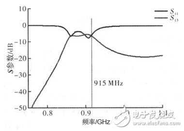
Figure 2. Antenna S-parameter simulation results
1.2, the design of the feed network
Generally, there are two feeding methods for the four-arm helical antenna, which are self-phase-feeding and power-sub-network feeding. Since the phase shifting mode is not easy to control, and the structure of the four antenna arms is different, the pattern is also slightly changed. Therefore, the power distribution network is selected to realize the feeding. The Wilkinson form of the splitter is larger in size, and the isolation resistance leads to increased losses, so a simple T-type splitter is used here. Figure 4 is a structural diagram of a power division network.
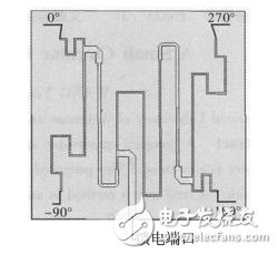
Figure 3, T-type power structure diagram
2. Simulation and measurement results of the antenna
Figure 5 shows the comparison of the simulated and measured standing wave results. It can be seen from the figure that the simulation and the measured results are in good agreement, and the antenna is UHF in China. The measured standing wave in the frequency range 920 ~ 925 MHz is below 1.2, and the standing wave in 908 ~ 928 MHz is below 1.5, which can meet the practical application. Figure 6 shows the variation of the antenna gain and the axial ratio with frequency. It can be seen that the peak gain of the antenna is 3.5 dB and the axial ratio is within the band of 2 dB. Figure 7 and Figure 8 show the normalized pattern of the antenna on the XZ and YZ planes. It can be seen from the figure that the 3 dB beamwidth of the antenna is 120°, and the front-to-back ratio is 15 dB. Figure 9 shows a physical picture of the antenna. The overall size of the antenna is 6 mln "60 mm "6 mm, which is smaller than a conventional RFID antenna. In summary, the antenna has superior performance and meets the requirements of the current UHF band RFID system for the antenna.
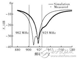
Figure 4, antenna standing wave simulation and test results

Figure 5. Antenna gain and shaft ratio as a function of frequency
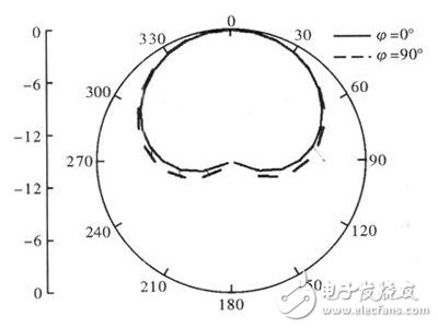
Figure 6. Two-dimensional normalized pattern of antenna XZ and YZ planes
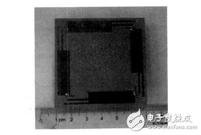
Figure 7, antenna physical map
3, the conclusion
In this paper, a small circularly polarized four-arm helical antenna is designed by using the new structure and coupling matching theory. The antenna can be applied to a radio frequency identification system in the UHF band. Compared with traditional RFID antennas, it has the advantages of small size, low profile, circular polarization and wide beam. After the production test, the measured and simulated results agree well.
Speakers with working frequency response range from 150~15000Hz are called full range speakers.


FAQ
Q1. What is the MOQ?
XDEC: 2000pcs for one model.
Q2. What is the delivery lead time?
XDEC: 15 days for normal orders, 10 days for urgent orders.
Q3. What are the payment methods?
XDEC: T/T, PayPal, Western Union, Money Gram.
Q4. Can you offer samples for testing?
XDEC: Yes, we offer free samples.
Q5. How soon can you send samples?
XDEC: We can send samples in 3-5 days.
Full Range Speaker
Full Range Speaker,Full Range Loudspeakers,Range Speaker,Small Full Range Speakers
Shenzhen Xuanda Electronics Co., Ltd. , https://www.xdecspeaker.com