Nothing to do, rummaging through the cabinet to find a routing transformer, pure winding mode adapter power supply is now rare, think about it, ready to do an inverter test, there is just an H-bridge module and an MCU small demo board.
Closer to home, first give the transformer a close-up:
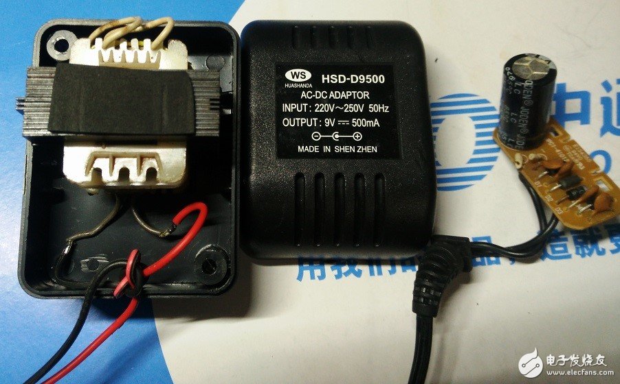
In the figure, the rightmost side is the removed rectifying plate, so that the transformer on the left side is a pure AC path, and the middle is the parameter, 500mA/9V.
The overall idea of ​​the test
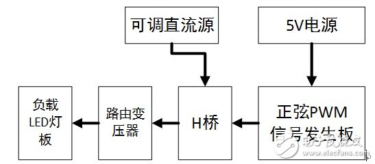
The MCU board calculates the sinusoidal PWM. After the H-bridge module's optical isolation and MOSFET modulate the power PWM, it is directly input to the low-voltage side of the transformer. The DC source of the H-bridge is about 10V (do not dare to make it too high, afraid of burning the transformer) ), the transformer outputs high voltage AC to supply power to the load. The load is an AC adapter, which is turned into a low-voltage supply of a small board with LEDs. This adapter and LED board act as loads (in other words, there is no such low power and can display AC loads).
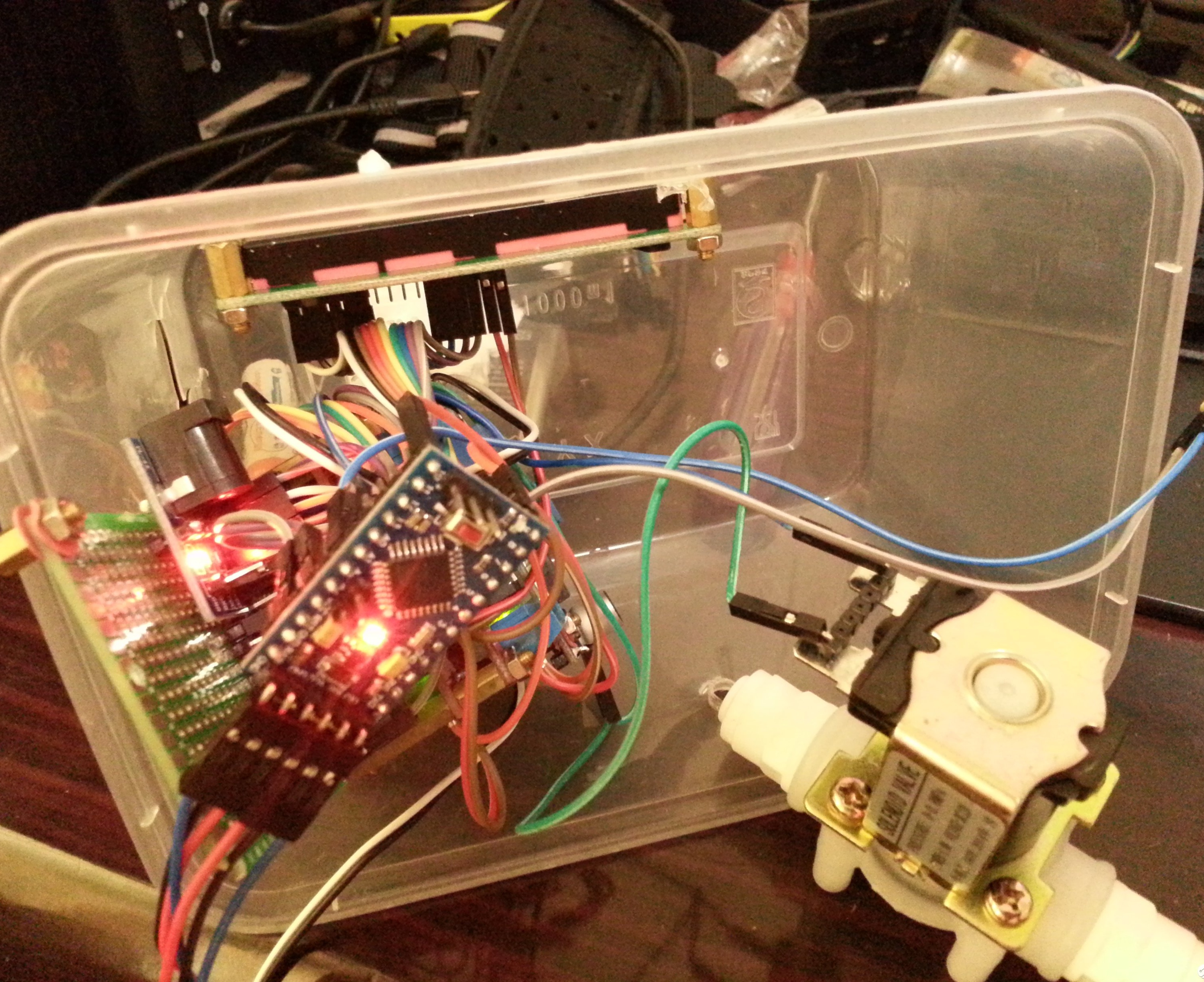
Let's take a look at the whole circuit of the test. Because it is a test, the wiring is messy.
Screenshot of the PWM waveform output from the previous H bridge
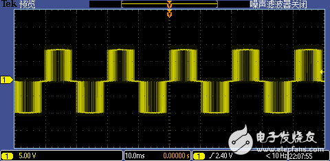
It can be seen that it is roughly sinusoidal modulation ~~~ (Adjusting the half-day program, the signal period is adjusted to 49.6Hz, the frequency division is not very good.)
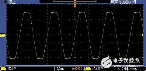
To determine the correctness of the sinusoidal modulation, look at the following figure: the voltage waveform of the output when the transformer is unloaded

I am very pleased to see this waveform, haha, pure sine wave, peak value 150V~~~
After the load is added, the waveform becomes ugly and is cut off (for the amplitude is high, the power supply voltage of the H-bridge is adjusted to about 11V), and the peak value of the output is also 150V. The reason for the clipping is probably as a load. Caused by the internal rectification of the power supply.
to sum up
It has been verified by experiments that the routing transformer plus the H-bridge can output a high-quality sinusoidal AC voltage under the modulation of a suitable signal source.
Since there is no voltage feedback loop, the inverter system cannot automatically change the PWM modulation waveform according to the load size, thereby keeping the output high voltage AC voltage stable; in addition, the capacity of the routing transformer is too small, if there is a large toroidal transformer, That's cool~~, according to the driving ability of the H-bridge, making an inverter close to 300W should not be a problem.
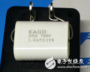
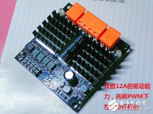
I almost forgot, this time successfully completed the test, the important components are high-voltage non-inductive filter capacitors (high-power IGBT modules are removed, the price is very expensive ~ ~), there is the H-bridge, working at 20kHz frequency, The output waveform is perfect (and one more, this product is a DC motor drive with dual outputs, only one of them is used in this experiment).
Banknote Value Counting Machine
Suzhou Ribao Technology Co. Ltd. , https://www.ribaoeurope.com