For the installation of capacitors, the first thing to mention is the installation distance. The capacitor with the smallest capacitance has the highest resonant frequency and the smallest decoupling radius, so it is placed closest to the chip. A slightly larger value can be a little farther away, and the outermost layer has the largest value. However, all capacitors that are decoupled from the chip are as close as possible to the chip.
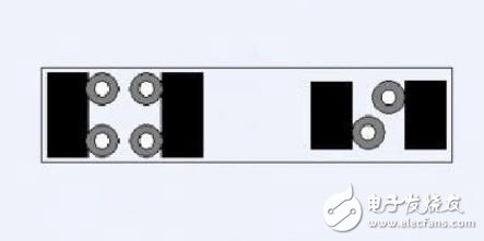
Figure 1 below is an example of a placement position. The capacitance level in this example generally follows a 10-fold hierarchical relationship.
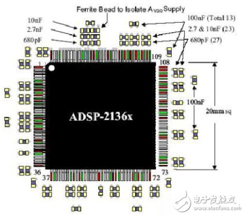
It is also important to note that when placed, it is best to distribute it evenly around the chip, for each level of capacitance. Usually, the chip is designed to take into account the arrangement of the power supply and ground pins, which are generally evenly distributed on the four sides of the chip. Therefore, voltage disturbances exist around the chip, and decoupling must also be uniformly decoupled from the area where the entire chip is located. If the 680pF capacitor in the above figure is placed on the top of the chip, due to the decoupling radius problem, the voltage disturbance at the lower part of the chip cannot be well decoupled.
Capacitor installation
When installing the capacitor, pull a small lead wire from the pad and connect it through the via hole and the power plane. The ground terminal is the same. The current loop through the capacitor is: power plane - "via" - "lead line -" pad - "capacitor - "pad -" lead line - "via" - ground plane, Figure 2 shows the current intuitively The return path.
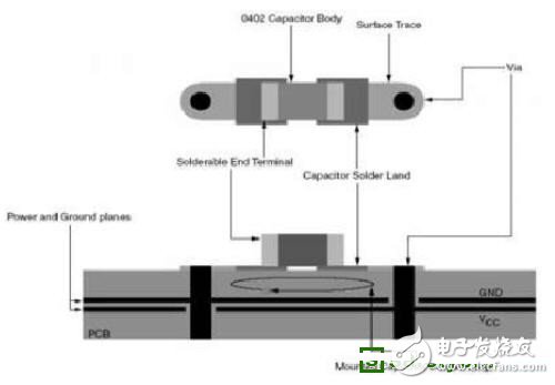
The basic principle of placing vias is to minimize this loop area and thus minimize the total parasitic inductance.
Figure 3 shows several ways to place vias.
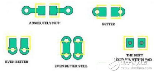
The first method draws a very long lead from the pad and then connects the via, which introduces a large parasitic inductance and must be avoided. This is the worst way to install.
The second method punctured the pad at both ends of the pad, which is much smaller than the first method and has a small parasitic inductance that is acceptable. The third type of hole punching on the side of the pad further reduces the loop area, and the parasitic inductance is smaller than the second one, which is a better method.
The fourth type is perforated on both sides of the pad. Compared with the third method, each end of the capacitor is connected to the power plane and the ground plane through the parallel connection of the via holes, which is smaller than the third parasitic inductance. Space allows, try to use this method.
The last method is to directly punch holes in the pad, and the parasitic inductance is the smallest, but the soldering may be problematic, depending on the processing capability and method.
The third and fourth methods are recommended.
One thing to emphasize is that some engineers sometimes use a common via for multiple capacitors in order to save space, and do not do this under any circumstances. It is best to find ways to optimize the design of the capacitor combination and reduce the number of capacitors.
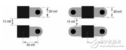
The wider the trace, the smaller the inductance, and the lead from the pad to the via is as wide as possible, if possible, as much as the pad width. So even with the 0402 package capacitor, you can use a 20mil wide lead. The lead wire and via mounting are shown in Figure 4, paying attention to the various dimensions in the figure.
For large-size capacitors, such as tantalum capacitors used for board-level filtering, the mounting method in Figure 5 is recommended.
All global AC input voltages are catered for from 100VAC to 240VAC single phase and US, AU, EU, UK, KR, CN interchangeable ac blade wall plug adapters are Class II rated(without earth pin). This high efficiency plug adapter is designed to provide customers with global solutions utilizing the latest in green power technology. The interchangeable power supply is also designed to meet UL CE FCC KC GS RoHS RCM SAA CB international certificates.

Power Plug Adapter,Multiple Plug Adapter,Interchangeable Plug Power Adapter,Detachable Plug Adapter,Multi Adaptor
Shenzhenshi Zhenhuan Electronic Co Ltd , https://www.szzhpower.com