How to connect the front USB cable to the motherboard, it is difficult for some newcomers. If you have a wrong connection, you can't use the USB device, but burn the USB device or the motherboard.
Because each USB interface can supply +5V500MA current to the peripherals, when we connect the onboard USB interface, we must strictly follow the motherboard's instruction manual. Never go wrong, otherwise it will burn the motherboard or peripherals. I believe that many friends have similar "smoke" when connecting the front USB cable. This requires us to accurately determine the order of the front USB cable. If we understand the basic wiring structure of the USB interface, then the problem is not solved.
First, let's take a look at the definition of each USB cable on the front of the chassis.
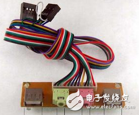
usually:
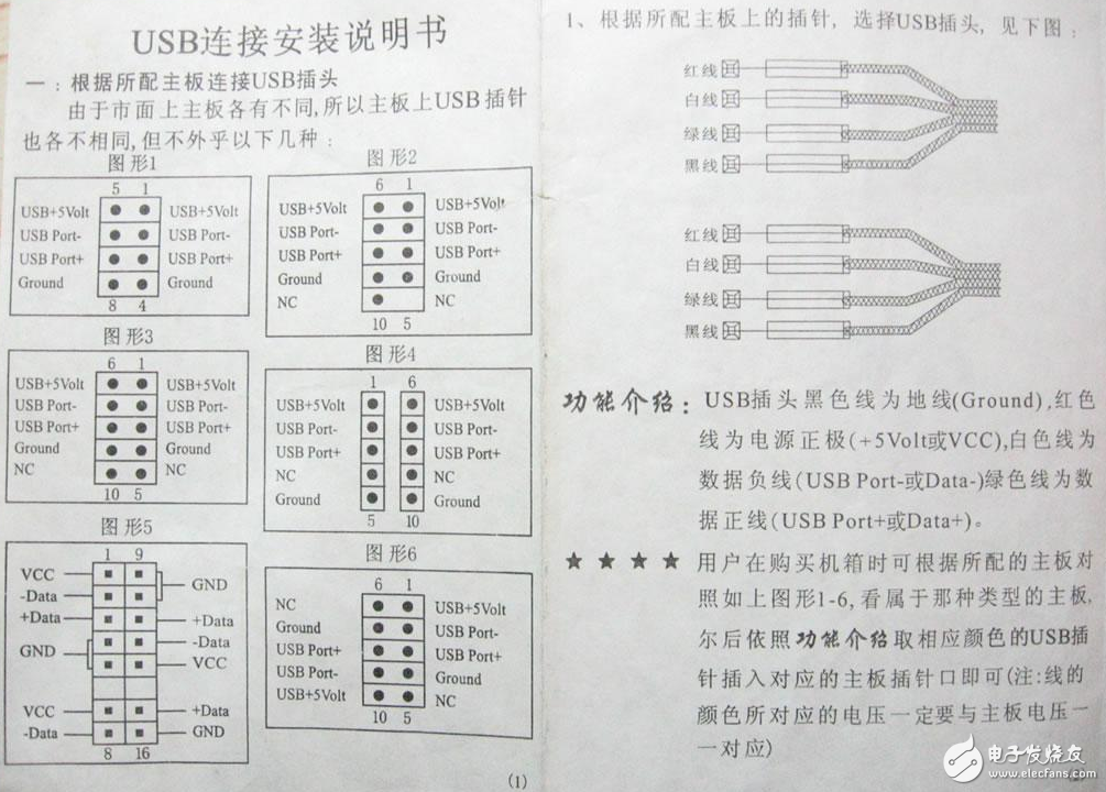
Red line: positive power supply (marked on the wiring: +5V or VCC);
White line: Negative voltage data line (identified as: Data- or USB Port -);
Green line: positive voltage data line (identified as: Data+ or USB Port +);
Black line: Ground (identified as: GROUND or GND).
Some chassis manufacturers are based on their own process design requirements, the color of the signal line will not be the same as described above, and considering the convenience, accuracy and versatility of the motherboard wiring, some chassis manufacturers will do USB cable On a module. Some chassis manufacturers take into account the versatility of the USB cable when connected to the motherboard, then spread the signal lines and identify each signal line, in order to adapt to many types of USB interfaces (described below). But no matter how the USB cable of the chassis is defined, as long as you understand how each pin of the front USB interface on the motherboard is defined, the USB cable will not be connected wrong!
Motherboard USB pin definitionLet's take a look at the USB pin definition on the motherboard. Although the definitions of the extended USB pins on the motherboards are different, there are only a few types and wiring methods:
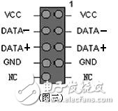
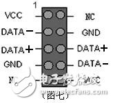
The first category: 8-pin type:
This type of pin is used for motherboards manufactured before 1999, but a few P4 (lower) motherboards currently use this type of pin.
Usually wiring method: insert the red wire into USB pin 1 and pin 2, and insert the remaining USB pins into the remaining USB pins in the order of Data-, Data +, GROUND (see Figure 1).
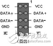
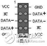
The second type of wiring is the opposite of the first set of wiring (see Figure 2).
The second category: 9-pin type:
This type of USB pin is mostly a newer motherboard, which is more common in motherboards that support the PenTIum 4 or Athlon XP chipset, especially those that support USB 2.0. This type of USB pin is more uniform and can be used with most motherboards.
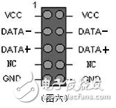
The third category: 10-pin type:
Most of the products using this pin type are motherboards that use i815, i815E, i815EP, KT133 and other chipsets. The connection method is much more chaotic than the first two types. In summary, there are roughly five ways to connect:
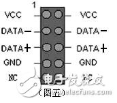
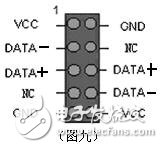
Generally speaking, pin 1 is the positive pole of the first group of USB power supply. The method of distinguishing pin 1 is to look at the logo on the main board. Some of them are directly marked with "1", some are black triangles or white thick lines. There are also some brands of motherboards. If two front USBs are connected to the USB device at the same time, one of them will not work properly. This is a bug in the motherboard. It is normal for the two front USBs to be used separately.
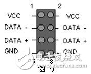
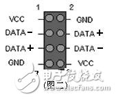
Chassis front USB wiring methodAt present, USB has become the interface with the most daily use. Most motherboards provide up to 8 USB ports, but generally only four are provided in the back panel. The remaining four need to be installed on the front USB port of the chassis. For ease of use. At present, the front USB interface is provided on the motherboard, as shown in the following figure:
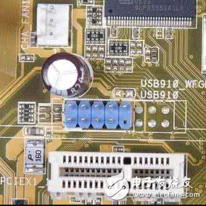
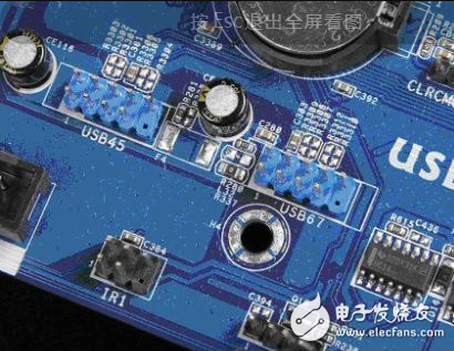
The figure above shows the front USB interface provided on the motherboard. For the above example, there are two sets of USB interfaces. Each group can be connected with two USB ports, which are USB4, 5 and USB6 and 7 interfaces. In total, four USB ports can be extended on the front panel of the chassis (of course, the chassis is required. Support, in general, the chassis is only available for two sets of front USB ports, so we only need to connect a group).
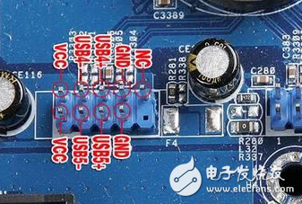
The picture above shows the front USB cable of the front panel of the chassis. VCC is used to supply power. USB2- and USB+ are the negative positive interface of USB and GND is the grounding wire. When connecting the USB interface, you must refer to the manual of the motherboard. Careful comparison, if the connection is not correct, it is easy to cause the motherboard to burn. The figure below shows the detailed connection method between the motherboard and the USB interface.
Many of the user interface products designed and manufactured by CSI will eventually live in extremely harsh environments. Some being exposed to UV exposure from the sun for days, months or even years at a time. Luckily, there are methods to protect the keypad from the effects of the sun. One of these methods is using a UV Resistant Coating.
A UV resistant coating is typically applied to the keys. The coating is glossy in appearance and looks very similar to epoxy coatings that were once used on membrane switches. The major difference between the UV resistant coating and the epoxy coating however, is that the epoxy was not durable. Over time, the epoxy not only became embrittled but it tended to discolor and yellow.
The UV resistant coating is designed with special barrier resins and compounds that are activated with ultraviolet light. Once activated, they prevent any damage from occurring to the coating or the base material of the keypad.
The UV resistant material`s [glossy-like" look also enhances the appearance of keypads. The glossy and clean look of the material really makes the product snap and stand out. Between the UV resistant benefits and the enhanced aesthetics, using the UV coating is really a no-brainer when designing a keypad that is going to be used outdoors.
Uv Resistant Membrane Switch,Button Type Membrane Switch,Membrane Switch Gnd Cable,Electrocardiograph Membrane Switch
Dongguan Nanhuang Industry Co., Ltd , https://www.soushine-nanhuang.com