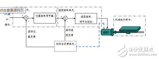
The servo drive system of CNC machine tools includes spindle drive and feed drive. There are two different types of devices, DC and AC. The fault phenomenon is roughly divided into three categories: the servo drive system of the CNC machine tool includes the spindle drive and the feed drive.
1. Handling drive system failure handling:According to statistics, the failure rate of this part accounts for about l/3 of the total failure rate of CNC machine tools. The fault phenomenon is roughly divided into three categories:
·Software alarm phenomenon: including servo feed system error alarm (mostly caused by failure of speed control unit or fault in the main control printed circuit board related to position control or servo signal), detection component (such as tachogenerator, rotation) Faults such as transformers or pulse encoders, faults caused by detection signals, and overheat alarms (including overheating of the servo unit, overheating of the transformer, and overheating of the servo motor).
· Hardware alarm phenomenon: including high voltage alarm (grid voltage instability), high current alarm (thyristor damage), low voltage alarm (mostly 85% of input voltage is lower than rated value or poor power supply connection), overload alarm (mechanical The load is too large), the speed feedback disconnection alarm, and the protection switch action is incorrect. These faults should be treated separately according to the specific situation.
· Fault phenomenon without alarm display: including machine out of control, machine tool vibration, machine tool overshoot (incorrect parameter setting), excessive noise (fault in motor), unstable at fast forward. These faults should be searched for the fault source from the aspects of checking the speed control unit, parameter setting, transmission gap, foreign matter immersion, motor axial yaw, and poor brush contact.

The failure of the spindle drive system has the following aspects:
• Faults in the DC spindle control system: including spindle stop rotation (trigger line fault), abnormal spindle speed (tachometer generator failure or digital/analog converter failure), main motor vibration or excessive noise (phase sequence is incorrect or The power frequency setting is incorrect), the overcurrent alarm, the speed deviation is too large (the load is too large, or the spindle is braked).
· AC spindle control system failure: including motor overheat fault (load exceeded, cooling system dirty, cooling fan damage, poor wiring between motor and control unit, etc.), AC input circuit and regenerative circuit fuse blown (such failure reason More: if the impedance is too high, the surge absorber is damaged, the power rectifier bridge is damaged, the transistor module used for the inverter is damaged, the control unit printed circuit board is damaged, the motor is added, the deceleration frequency is too high, etc.), the main motor vibration and noise are too large The motor speed exceeds the standard or fails to reach the normal speed.
To treat these faults, you must first find out the fault source from the beginning of the test, find and analyze the cause of the fault, and take measures to eliminate the fault. If the motor vibrates, it must first confirm under what circumstances this phenomenon occurs. If it occurs during deceleration, the fault must occur in the regenerative circuit. At this time, it is necessary to check whether the fuse of the circuit has been blown, or the loop Is the transistor damaged? If it is generated at a constant speed, first check whether the feedback voltage is normal, then cut off the command to see if there is abnormal noise during the motor stop. If so, it is certain that the fault occurred in the mechanical part, otherwise it is on the printed circuit board. If the feedback voltage is not normal, you should first check whether the vibration period is related to the speed. If it is related, check whether the connection between the spindle and the spindle motor is faulty. Is the spindle and the pulse generator installed at the end of the AC spindle motor damaged? No, it is possible that the fault is generated on the printed circuit board and the board needs to be viewed or re-adjusted. It may also be mechanically and is a mechanical failure.
In short, the handling of faults in the drive servo system requires patience, subtle inspection, testing and analysis. Of course, it is easier to judge when the experience is accumulated.
Copper Lugs,Copper Cable Lugs,Plating Copper Cable Lugs,Copper Tube Terminal Lugs
Taixing Longyi Terminals Co.,Ltd. , https://www.txlyterminals.com